Tek-Tips is the largest IT community on the Internet today!

Members share and learn making Tek-Tips Forums the best source of peer-reviewed technical information on the Internet!

  • Congratulations JAE on being selected by the Eng-Tips community for having the most helpful posts in the forums last week. Way to Go!

Raft on piles

M.hagag

Structural
Joined
Jun 24, 2025
Messages
4
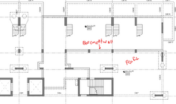
Hi all, I have a suspended raft on piles which is supported on some of its edges by basement walls, I noticed some piles reactions are way less than columns reactions they are supporting, my assumption is that due to the presence of the rigid retaining wall, anyone faced a similar issue , please refer to attachment for more detail1750802219052.png
 
Are the walls underneath the slab or above it?

You have to be very careful with mixing and matching raft/piles and walls/strip footings
I have been dealing with a damaged house that has a basement with this system...the walls have settled far more than the piled foundations and there is now a 50mm+ hogging pattern in the floor and the 400mm thick slab is busted up

You haven't given enough information here to really understand the issue. All we can see is "potentially" the basement walls are contributing to the walls not matching what you expect...or it could be an error in your modelling....
 
I assume the basement walls are under the raft. I assume the columns you mention are the solid shaded areas over the pile caps. I agree with Greenalleycat, mixing foundation systems tends to create an additional set of uneven settlement issues beyond the typical ones all structures face.

In addition to the difference in support, how reliable is the presence of the loads in each combination? To model 50 psf here with 30 psf there, and then get some different real-life mixture adds to the complexity.

Still need a better description of what is what in your drawing.
 
The soil condition cannot differ such much to require a pile under some columns and strip footing (not shown assuming) 5 meter away from the piles. Probably there is higher forces on the columns with piles. This should be the reason. Otherwise, you need to provide more information.
 
Thanks all for your helpful thoughts, looks like the original post is missing some information for you to get my point (sorry about that) here are some photos with some additional info so you can help me better
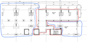
1- the area inside the red boundary is a suspended slab at ground floor levels supported on the basement wall so it's the basement floor cover slab, while the area inside the blue boundary is the raft on piles slab at same level ground floor so its supported on piles and in same time supported on basement walls going down to basement level 1750959408615.png
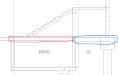
2- a section to clarify point number 11750959625245.png
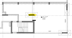
3- going back to the question in the original post this highlighted column reaction under own weight only is around 4000KN, while the two piles supporting it are reporting around 1400KN each which is not making sense to me so what I made in analysis that I weakened the retaining wall and then I started getting more reliable results , so is that approach ok or Iam missing something.
1750959924189.png
thanks again for your precious help.
 
I have run into similar (but not exactly the same) circumstances before. Situations where the stiffness of the structure caused a load re-distribution at lower levels that would not agree with what the same location at a higher level would get. In my case, it was shear walls where the upper levels had only one set of shear walls, but the lower levels had more shear walls.

In my case, I designed the LOWER shear walls for the larger of the two loads that I got from the analysis (meaning if the wall had 100kips of shear at level 1, but 180 kips at level two then I would assume that the 180 kips continued down through the wall (with an increased moment as well). But, I would still design the other walls as if the 80 kips got re-distributed to them.

This is one of those "engineering judgment" calls that you sometimes make to "over rule" the output you get from a structural analysis program. Remember, your computer model is just a convenient model to help you design. When it gives you questionable results, it is good practice to let your engineering knowledge / experience guide you to a more conservative design.

Note: I also think it is probably wise to "disconnect" the pile supported foundation from the non-pile supported one in your structural models. It seems odd to share loading between two drastically different types of foundations.... If I were to keep them together, I'd want to get some recommendations on how to model this from the Geotechnical engineer.
 
Possible reasons I can think of are:

1) If soil is modelled as springs, check the soil stiffness under piles. For indirect checking check if the slab making excessive deflections under column base.

2) If soil is not modelled with springs and instead supports are placed under the footings and piles, check if the stiffness correctly entered for the slab. It can be thickness or wrong modulus of elasticity causing high stiff slab carrying the columns instead of piles.

3) Check if there are similar problems at other piles.

Generally, deflection check of the model under different loads helps to understand such kind of problems.
 
I have run into similar (but not exactly the same) circumstances before. Situations where the stiffness of the structure caused a load re-distribution at lower levels that would not agree with what the same location at a higher level would get. In my case, it was shear walls where the upper levels had only one set of shear walls, but the lower levels had more shear walls.

In my case, I designed the LOWER shear walls for the larger of the two loads that I got from the analysis (meaning if the wall had 100kips of shear at level 1, but 180 kips at level two then I would assume that the 180 kips continued down through the wall (with an increased moment as well). But, I would still design the other walls as if the 80 kips got re-distributed to them.

This is one of those "engineering judgment" calls that you sometimes make to "over rule" the output you get from a structural analysis program. Remember, your computer model is just a convenient model to help you design. When it gives you questionable results, it is good practice to let your engineering knowledge / experience guide you to a more conservative design.

Note: I also think it is probably wise to "disconnect" the pile supported foundation from the non-pile supported one in your structural models. It seems odd to share loading between two drastically different types of foundations.... If I were to keep them together, I'd want to get some recommendations on how to model this from the Geotechnical engineer.
Hi Josh thanks for your reply, my first thoughts indeed were to separate the raft slab from the basement slab and have the columns terminating at -1m from ground floor on isolated pile caps with 3 piles or more for each but the issue is the water table as this is a beach front structure where the ground water is only 1m below ground floor level and the owner doesn't want any kind of permanent shoring even suggested raising the ground floor slab level to allow for some sort of a column neck below the slab but unfortunately the architects fought back against this proposal , any way will try to use my Judgement here like you suggested .... Thanks again
 
Possible reasons I can think of are:

1) If soil is modelled as springs, check the soil stiffness under piles. For indirect checking check if the slab making excessive deflections under column base.

2) If soil is not modelled with springs and instead supports are placed under the footings and piles, check if the stiffness correctly entered for the slab. It can be thickness or wrong modulus of elasticity causing high stiff slab carrying the columns instead of piles.

3) Check if there are similar problems at other piles.

Generally, deflection check of the model under different loads helps to understand such kind of problems.
Hi Liam thanks for your reply, for point number 1 soil is not considered as support as per geotechnical recommendations, point 2 -slab thickness / material is OK , point 3- only piles under columns near the basement walls have same issue, however when I significally decreased the basement wall stiffness in the analysis model the sum of piles reactions became more closer to the supported column reaction plus the raft slab and the pile cap weight , so Iam thinking of having two models to extract results from one with walls with default stiffness where I can get accurate values for slab reinforcement and deflection , the other one with reduced stiffness for walls where I can get some piles reactions that makes sense , would be happy to hear your thoughts about this and thanks again.
 
Hi Josh thanks for your reply, my first thoughts indeed were to separate the raft slab from the basement slab and have the columns terminating at -1m from ground floor on isolated pile caps with 3 piles or more for each but the issue is the water table as this is a beach front structure where the ground water is only 1m below ground floor level and the owner doesn't want any kind of permanent shoring even suggested raising the ground floor slab level to allow for some sort of a column neck below the slab but unfortunately the architects fought back against this proposal , any way will try to use my Judgement here like you suggested .... Thanks again
The danger is a differential settlement between the two types of foundations leading to cracking in the slab and such. Regardless, I would still design the pile portions of the foundation as if they were not connected if that leads to higher pile forces. Then design the slab as if they are connected... Just to be conservative with my design.

Alternatively, it might be worth adding a joint between the two foundation types that allows for shear transfer, but not moment.

I was a witness to (but didn't work on) a project where the floor slab was isolated from the footings by adding a diamond shaped joint around the columns. Allowing the footing to experience settlement without affecting the levelness of the floor slab.
 

Part and Inventory Search

Sponsor

Back
Top