mfgenggear,
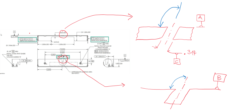
Where you place the datum feature flag is important. It can mean the center or just one face.
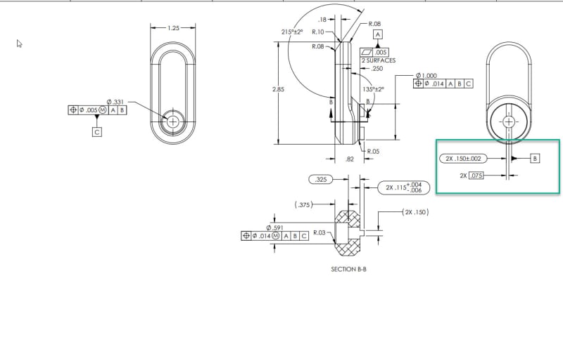
Flatness control is correct, but it does not control the relationship between the 2 surfaces. I would think the engineer should want to control the coplanarity. Since flatness only controls the form (coplanarity is a locational relationship). Both surfaces could be .005 or less flat (and pass inspections), but they could be offset from each other, let's say 1 in apart. And the part would still pass because you are only verifying the flatness. I hope this makes sense.
And the same applies to the 2 tabs. Just because they are shown inline on the drawing, it does not mean they will be coincident when manufactured. A positional callout without any datum reference should be used. Or you could remove "2X", keep the size tolerance, add the <CF> modifier (no need for a position callout as there would be only 1 continuous feature of size).