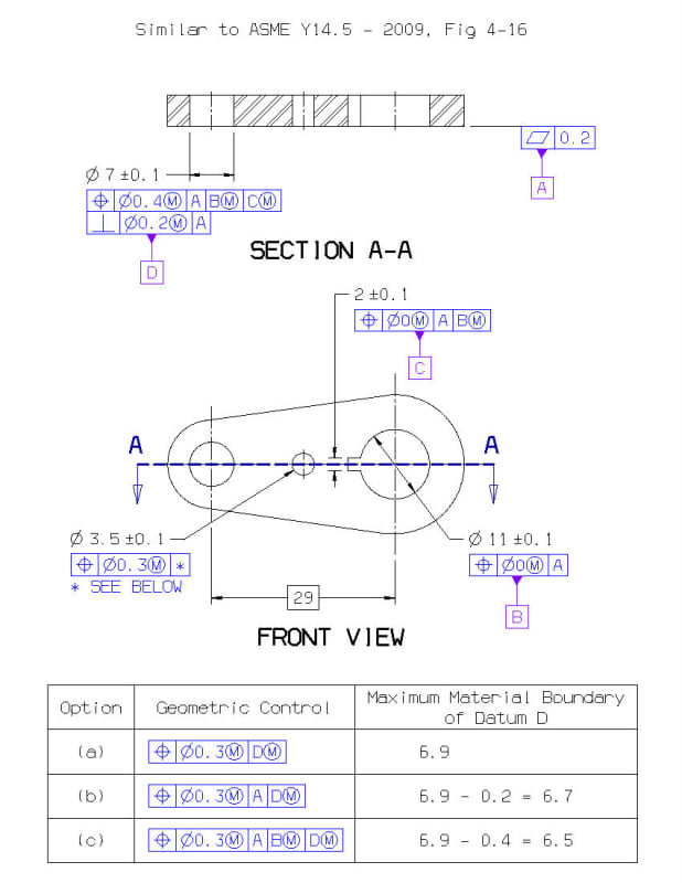
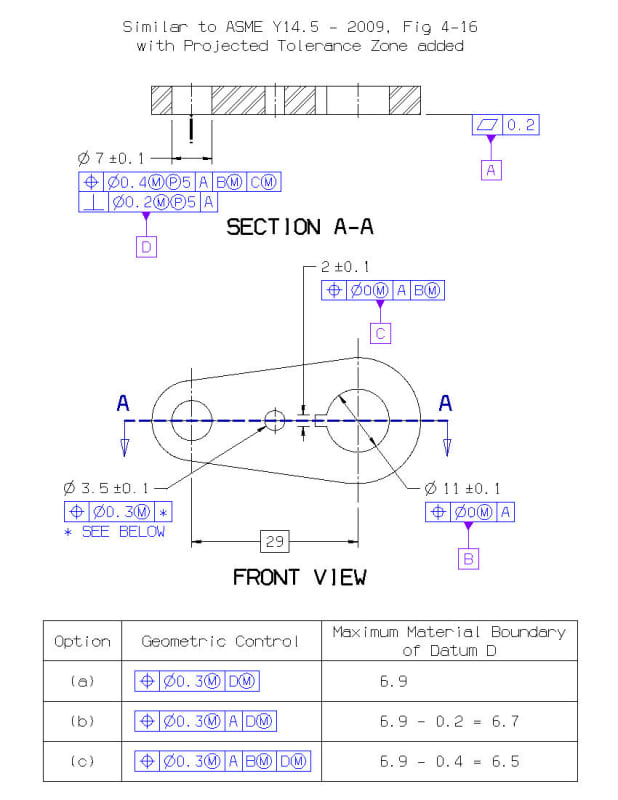
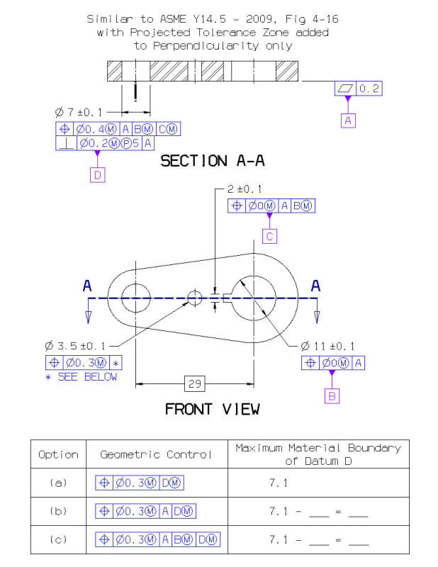
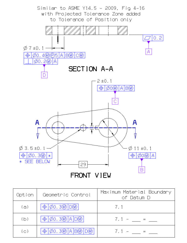
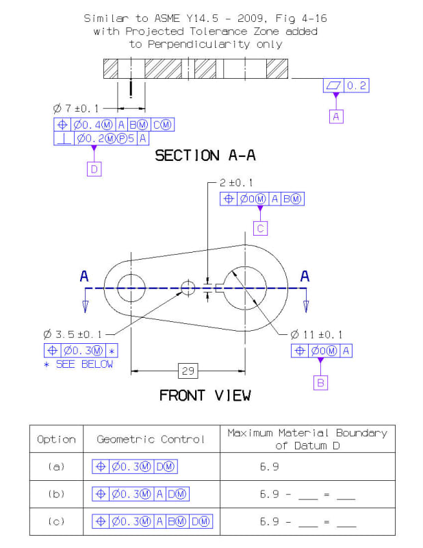
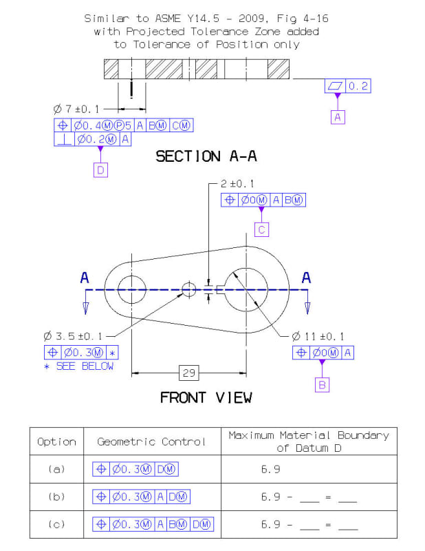
Pins being pressed into the parts are showing a 'drift', rather than assuming the c/l of the hole being pressed into.
I fail to see the connection between this and your MMC / MMB questions.
Are you trying to to determine the proper tolerances to ensure some particular functionality, or are you just stuck trying to interpret a drawing you have no control over? What is your goal?
The hunch is that the application of the PTZ to refine the perpendicularity is allowing it to actually be fabricated with the 'drift' predisposed into the process. Picture the portion of the perpendicularity in the positional tolerance zone, but when it gets to the projected zone, it is no longer bound by the positional zone, almost as if the PTZ tolerance can be added to the positional, rather than a refinement within the positional as Perpendicularity is wont to do, less the PTZ modifier.
Adding a perpendicularity tolerance will not make a position tolerance less restrictive. The two tolerances must both be met, and they can generally be considered independently.
Would you say that for projected position the virtual condition in this case would be the movable boundary defined by the verification volume, or instead a boundary fixed at basic location/orientation relative to the DRF?
Who knows. ASME Y14.5-2009 Section 7 implies that "virtual condition" is the tolerance boundary itself, and that it's located at true position. This is incompatible with the Y14.5.1M-1994 definition of MMC projected tolerances. The term is never used in Section 4 regarding datum feature references, so perhaps it doesn't really matter for the topic at hand.
When you say "whether it defines the datum simulator geometry" are you suggesting that different interpretations are possible?
I am suggesting that for the MMB modifier to make sense on a datum feature reference, the standard needs to define the geometry of the datum feature simulator that would be used. An attempt to do that is made, but unfortunately it's spread across multiple paragraphs that don't seem to fit together quite right.
I guess I just thought it strange that all the examples for projected tolerance utilize MMC when in my mind in most cases RFS, while more difficult to gauge, would better reflect the assembly condition.
Even stranger is that the "This on the drawing" portions of Y14.5-2009 Figs. 7-21 and 7-22 have MMC modifiers, but the "Means this" portions appear to describe RFS tolerances.
As far as I can tell, Y14.5-2009 never attempts to define the meaning of MMC projected tolerances. It doesn't give much of an explanation for RFS either, but the intended meaning is easy enough to guess in that case.
pylfrm
