sorry to disagree with you Burunduk, you are not correct.
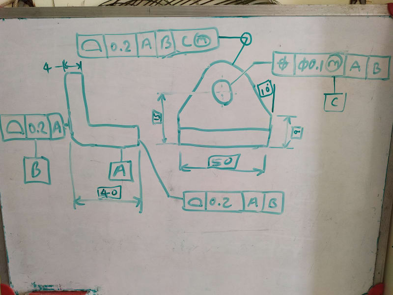
[highlight #EF2929]quote "If position tolerances are applied with an MMC modifier the way it is in this example a fixed size gage of the VC size can be used for the position inspection per the surface interpretation. Once prepared, utilizing a fixed size gage is cheaper and quicker than using a CMM."[/highlight]
I said it was possible in an another post to use a gage it was un acknowledged, I never said it was not possible. but the quantity of parts has to justify cost. for low quantity of part it is absolutely not cheaper, the cost of the gage has to be amortized by the quantity of parts to lower price per part.
I estimate for a living, The has to be enough quantity of parts to justify it. for a small lot of parts, a CMM is faster and cheaper.
[highlight #EF2929]quote "As far as profile tolerances go, I disagree that they always require a CMM. For example, if profile control for tolerancing of the small face at 40 basic from B was referencing only B that would be a very simple callout to inspect and it wouldn't require much more than a surface plate, a height gage, and some gage blocks available at every machine shop. This may be adequate enough for the function too" unquote[/highlight]
I never said Verifying true position and profile could not be done manually, but it is a PITA, because I have done it. it is much easier to use a CMM,
and any inspector will know it faster, easier and more precise with a CMM,
surface plate inspect of profile of surface is a PITA, again I did not say it could not be done, the fact of the matter using individual control of
attributes is much easier , at RFS than using MMC, and LLC on perpendicular, flatness, and etc. Because I have done it.
I did leave out that an other option for profile is a optical comparator that is calibrated and precise, use a Mylar template at magnification of significant size, 10X 20X size as long as the tolerance permits or the comparator is precise enough, again done that being there.
I am old experience Inspector, certified and ex NDT level 2 NDT inspector.
That said, am I always right no and we never cease learning even old dogs, have to keep up with the changes. and need retraining as the times change, new equipment, new skills,
any who thinks they know it all are fooling them selfs.
[highlight #EF2929]quote" Contrary to what many think a surface plate and a height gage are not a precise and theoretically correct way to inspect +/- tolerances because this method doesn't provide two point measurements or "actual local size" per ASME Y14.5, but what they do provide is inspection relative to a datum (simulated by the surface plate). Furthermore, +/- toleranced size dimensions require opposed points for measurement but there is only a limited area on datum feature B at which opposed points to the left-hand surface exist. That may lead to a very partial distance verification between the two vertical surfaces. The standard doesn't cover these situations well enough if at all." Unquote[/highlight]
it depends on the skill level of the machinist and the inspector, One can not rely on the accuracy of the height gage, it will have error due to wear.
the key is certified gage blocks, a working set and a master set. in my field it is standard practice to use gage blocks to set the height gage.
depending on the precision of the tolerances of attributes eg lengths, and diameters
example stack up gage blocks ( and there is a procedure for this) for the length required on a certified surface plate. set the dial indicator
to zero off the gage block. this will be the nominal setting, now use the certified dial indicator for the max and min values.
this is fast and very accurate, inspect to the required AQL level good to go, can a CMM do this yes, but not as fast, but that could be debated,
now it is always better to locate on the datums of the part, but in real life it is not always possible, then tooling surfaces have to be established
that are precise to the datums, take into account of any stack up issues. I say this with prejudice a drawing that is correct may be correct by the ASME
specification, may not, I repeat not be correct for manufacturing feasibility. but most engineers don't care as long as it is made to the requirements.
as it should be.
what's even faster is a laser system which I can not comment( no experience with laser, only theodolite optics for installations for aircraft and rockets) but I seen videos and they are fast and accurate.
the method of inspection will be dictated by size of the parts.