Continue to Site

Eng-Tips is the largest engineering community on the Internet

Intelligent Work Forums for Engineering Professionals

  • Congratulations cowski on being selected by the Eng-Tips community for having the most helpful posts in the forums last week. Way to Go!

Profile tolerance

Status
Not open for further replies.

Sa-Ro

Mechanical
Jul 15, 2019
279
Hi

IMG_20200719_121641_ppxthe.jpg


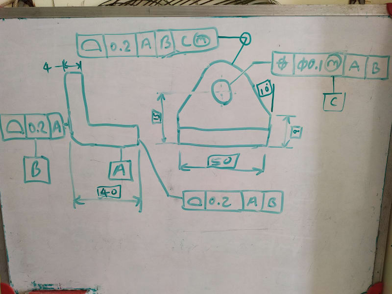
Design requirements:
Datum B surface shall be perpendicular to datum A.

Hole shall be perp to datum B and located from datum A.

Length 50, 9 height, angular, radius shall be equally separated from hole axes.

Did I used correct GD&T?

Shall I use all around with datum B to control the 4 and 40
 
Replies continue below

Recommended for you

"Hole shall be perp to datum B"

Then you may want to switch between the A and B in the position callout to make B primary and A secondary. Any planar surface you choose as a primary datum feature will constrain 2 rotational degrees of freedom and set the orientation of the feature you are controlling, so if you want the perpendicularity to B to be directly reflected by the position tolerance zone and not influenced by how much datum feature B is perpendicular to A, B should be primary.

Another issue is the all-around symbol at the 0.2 profile tolerance which is with reference to |A|B|C(M)|. With all-around, you include the bottom face - datum feature A in the tolerance zone. This doesn't seem to be your intent per the design requirements description.

"Shall I use all around with datum B to control the 4 and 40"

No. That would create a complex datum feature B that doesn't seem to be part of your design requirements. The profile tolerance on the face located at 40 from B and a direct tolerance (if that's the intent) on 4 is fine.
 
So I will mention point A and B at two ends of length 50 and mention A to B below 0.2 profile tolerance which is with reference to |A|B|C(M)|. With all-around.

Thank you.
 
@SA-RO

it is important as well to look at the form, fit and function of a part.
I take it Datum -A- & -B- will be important to locate on a mating part.
it is important that these surface are square, ask your self why is it important to control profile of the surface?
would a simple perpendicular @ RFS not suffice, with a separate wall thicken tolerance requirement.
as drawn the opposite face of datum -B- why is it important to control the profile of the surface. does it locate an other part?
or it does nothing but for edge distance.
when fit for function of the part is required then do as it is required.
but over tightening of tolerance will require tighter machining and inspection thus cause to be more expensive in cost.
keep it simple, don't over tolerance when not needed. simple dimensioning widths and lengths will simplify
machining and inspection.
just to add I believe the true position of the hole and profile of the radius and angle is a good call.
 
To rational my previous post.
Each type of GD&T requires and inspection equipment in measurement. And fabrication.

Holes with true position as well as profile
Will require a CMM.

A tolerances dimension can be done with micrometer, calipers or CMM.

CMM are in high demand, and are always busy. If simple hand tools or height gage
Is used to inspect parts it will free up the CMM for more difficult parts.
A machinist can verify their part as they machine it not requiring to submit for CMM
Inspection.
Keep this in mind when dimensioning parts.
If this is only for learning just keep in mind for real parts.
Go to the floor and educate your self what
Is required to inspect parts in the real parts.
 
Sa-Ro said:
So I will mention point A and B at two ends of length 50 and mention A to B below 0.2 profile tolerance which is with reference to |A|B|C(M)|. With all-around.

Your conclusion about the need for the between symbol is correct. Just to make sure it's clear - that profile callout is now with all-around. Once you label the limiting points with letters and use the between symbol the all-around symbol should be removed. The between symbol tells what surfaces the tolerance applies to.
 
"Holes with true position as well as profile
Will require a CMM."

If position tolerances are applied with an MMC modifier the way it is in this example a fixed size gage of the VC size can be used for the position inspection per the surface interpretation. Once prepared, utilizing a fixed size gage is cheaper and quicker than using a CMM.

As far as profile tolerances go, I disagree that they always require a CMM. For example, if profile control for tolerancing of the small face at 40 basic from B was referencing only B that would be a very simple callout to inspect and it wouldn't require much more than a surface plate, a height gage, and some gage blocks available at every machine shop. This may be adequate enough for the function too.
Contrary to what many think a surface plate and a height gage are not a precise and theoretically correct way to inspect +/- tolerances because this method doesn't provide two point measurements or "actual local size" per ASME Y14.5, but what they do provide is inspection relative to a datum (simulated by the surface plate). Furthermore, +/- toleranced size dimensions require opposed points for measurement but there is only a limited area on datum feature B at which opposed points to the left-hand surface exist. That may lead to a very partial distance verification between the two vertical surfaces. The standard doesn't cover these situations well enough if at all.

mfgengear, am I wrong in the above assessment?
 
sorry to disagree with you Burunduk, you are not correct.

[highlight #EF2929]quote "If position tolerances are applied with an MMC modifier the way it is in this example a fixed size gage of the VC size can be used for the position inspection per the surface interpretation. Once prepared, utilizing a fixed size gage is cheaper and quicker than using a CMM."[/highlight]

I said it was possible in an another post to use a gage it was un acknowledged, I never said it was not possible. but the quantity of parts has to justify cost. for low quantity of part it is absolutely not cheaper, the cost of the gage has to be amortized by the quantity of parts to lower price per part.
I estimate for a living, The has to be enough quantity of parts to justify it. for a small lot of parts, a CMM is faster and cheaper.

[highlight #EF2929]quote "As far as profile tolerances go, I disagree that they always require a CMM. For example, if profile control for tolerancing of the small face at 40 basic from B was referencing only B that would be a very simple callout to inspect and it wouldn't require much more than a surface plate, a height gage, and some gage blocks available at every machine shop. This may be adequate enough for the function too" unquote[/highlight]

I never said Verifying true position and profile could not be done manually, but it is a PITA, because I have done it. it is much easier to use a CMM,
and any inspector will know it faster, easier and more precise with a CMM,
surface plate inspect of profile of surface is a PITA, again I did not say it could not be done, the fact of the matter using individual control of
attributes is much easier , at RFS than using MMC, and LLC on perpendicular, flatness, and etc. Because I have done it.
I did leave out that an other option for profile is a optical comparator that is calibrated and precise, use a Mylar template at magnification of significant size, 10X 20X size as long as the tolerance permits or the comparator is precise enough, again done that being there.
I am old experience Inspector, certified and ex NDT level 2 NDT inspector.
That said, am I always right no and we never cease learning even old dogs, have to keep up with the changes. and need retraining as the times change, new equipment, new skills,
any who thinks they know it all are fooling them selfs.

[highlight #EF2929]quote" Contrary to what many think a surface plate and a height gage are not a precise and theoretically correct way to inspect +/- tolerances because this method doesn't provide two point measurements or "actual local size" per ASME Y14.5, but what they do provide is inspection relative to a datum (simulated by the surface plate). Furthermore, +/- toleranced size dimensions require opposed points for measurement but there is only a limited area on datum feature B at which opposed points to the left-hand surface exist. That may lead to a very partial distance verification between the two vertical surfaces. The standard doesn't cover these situations well enough if at all." Unquote[/highlight]

it depends on the skill level of the machinist and the inspector, One can not rely on the accuracy of the height gage, it will have error due to wear.
the key is certified gage blocks, a working set and a master set. in my field it is standard practice to use gage blocks to set the height gage.
depending on the precision of the tolerances of attributes eg lengths, and diameters
example stack up gage blocks ( and there is a procedure for this) for the length required on a certified surface plate. set the dial indicator
to zero off the gage block. this will be the nominal setting, now use the certified dial indicator for the max and min values.
this is fast and very accurate, inspect to the required AQL level good to go, can a CMM do this yes, but not as fast, but that could be debated,
now it is always better to locate on the datums of the part, but in real life it is not always possible, then tooling surfaces have to be established
that are precise to the datums, take into account of any stack up issues. I say this with prejudice a drawing that is correct may be correct by the ASME
specification, may not, I repeat not be correct for manufacturing feasibility. but most engineers don't care as long as it is made to the requirements.
as it should be.

what's even faster is a laser system which I can not comment( no experience with laser, only theodolite optics for installations for aircraft and rockets) but I seen videos and they are fast and accurate.
the method of inspection will be dictated by size of the parts.

 
mfgenggear,
I think it is good that you brought up the advantages of CMM in certain situations such as small lots of parts.
Since CMM may have an advantage over fixed gages for position inspection, there is a high probability that any part with a position tolerance on one of the features is going to pass through the CMM station anyway. That means there is no reason to worry too much about the other controls being too tricky for inspection with simple hand tools. The CMM will deal with them just as easily as with the position requirement inspection.

Specifically regarding profile versus +/- tolerances, I may have been misunderstood. As I mentioned but perhaps didn't emphasize enough: checking +/- toleranced dimensions using a surface plate, height gage and gage blocks is incorrect and it's not even a matter of precision or skills. I repeat: +/- toleranced dimensions are supposed to be checked by two point measurements between opposed points per the Actual Local Size definition - examples for measurement devices are calipers, micrometers and CMM (for CMM there is another option other than two point measurements and that is the swept spheres concept from the mathematical definition standard Y14.5.1M, less commonly applied in the industry). What can be said for sure is that +/- tolerances do not involve datums and are not supposed to be verified relative to simulated datums. The surface plate is a datum feature simulator so it shouldn't be used for +/- inspection.
Like you, I certainly do believe that other than the functional requirements and considerations the designer should keep in mind manufacturing and inspection feasibility and know what metrology tools are available at the manufacturing unit that will work per his drawings. If he plans that the requirement will be verified by the height gage and the surface plate and it suits the function, a profile tolerance referencing a planar datum feature should be the control of choice.


Agreed Burunduk
On gear shafts we love centers.
All of our parts use centers.
We used custom precision ground surfaces
That locate on the surface plate.
These bench centers were like a combination
90 degree angle plate. And could be set horizontal or vertical. All surfaces were grind and lapped. Less than .00001 error.
These were used to verify run-out, perpendicularly, cylindricity, squareness.
And were used with machinest precision dial indicator base, and indicator.
Used with height gage. And worked very well
For cylindrical rotating parts.
This old school but was very quick and precise.
But these were being used way before
I was born. And is still being used for
Gear industry. Because it works.
When I started we were using slide rules,
And drafting boards.
I am ancient, master plaster to verify an coordinate all tools for aircraft
Computers did not exist. Funny.
A big jump for all our industry. Was the use of computers for cad and cam.
And the CMM. I am living history of how this industry has progressed through the years.
Every product requirements are diffrent
And I need to keep reminding my self of that. I need to listen more and talk less.
 
mfgengear,
I definitely don't think you should talk less as you share some very valuable insight that is based on your long experience.

I acknowledge that when the form of the relevant surfaces is accurate enough such as with the lapped sides made to this very high precision as you mentioned, a height gage measurement with the reference being the surface plate and gage blocks gives an estimation of the actual local size with an insignificant error.
 
Bunduruk

When it is not condusive to use a precision bench centers, there are other precision tools
That aid in inspection.
123 blocks
V blocks are very popular.
Many different size rings with holes.
And when necessary ground fixtures or arbors.
Such as required for planetary ring gears.
Little diffrent than for housings.
Which requires a whole set of diffrent tools.

Waiting for lasers to replace existing methods.
With manufacturing progressing at an accelerated rate, now can probe the machined surface it can now input the correct geometry and stock removal.
Production rates are unbelievable.
 
Status
Not open for further replies.

Part and Inventory Search

Sponsor