Continue to Site

Eng-Tips is the largest engineering community on the Internet

Intelligent Work Forums for Engineering Professionals

  • Congratulations waross on being selected by the Eng-Tips community for having the most helpful posts in the forums last week. Way to Go!

Primary Datum Material Modified

Status
Not open for further replies.

T. Hinkle

Mechanical
Oct 27, 2016
3
GDT_Question_npveri.jpg


In the attached image, what does it mean when B is material modified? With both B and C datums material modified does that allow for .002 datum shift? Is this allowed per the standard?
 
Replies continue below

Recommended for you

T. Hinkle,

Your drawing appears to have been done to ANSI Y14.5M-1982. I am more familiar with the later versions of this, and there may be stuff I am missing.

The circle[ ]M stands for Maximum Material Condition. In the case of your datums[ ]B and[ ]C, these would be fixtured by pins .058" and .0388" respectively. The datum[ ]C[ ]pin would be diamond shaped. If the holes are larger than the minimum, you have some wiggle room to position your part at inspection time.

The drawing is badly prepared. Datum[ ]A should be applied to the top or bottom face. Applied to the edge, it is redundant.

--
JHG
 
Drawoh,

Thanks for the reply. I agree the drawing is badly prepared and Datum A should be a face(which they are probably using during inspection process). Seems like the designer placed MMC modifiers at every possible location. After looking thru the 73&82 standards, I do see primary datums with MMC, but have not seen a primary and secondary datum at MMC within the same Feature Control Frame. Does this violate any of the rules or just make inspection harder?
 
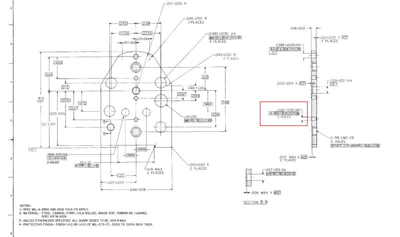
It clearly says MIL-A-2550 and ANSI Y14.5-73; That's why the datum references are to the left of the tolerance.

What the callout means is that the part is not necessarily held with the face of the plate perpendicular to the pins that simulate A and B - think of it like the part is going to be impaled on spikes - the callout means that all the spikes go through the plate at the same time. I think there was some leftover notion of the implied datums, but I think that they don't work when the datums are explicit. They may also have been counting on the default angle tolerance to limit perpendicularity.

Most odd is the reference to datum A at MMC in defining datum C, since A is a face of the part, not one with size.

It looks like it was generated by a and whatever the previous maker did to make parts that worked is not represented by this drawing. As I commented elsewhere, too many are self taught and had bad teachers. I would not be surprised if there were calls and memos from the supplier about changes he needed to make to the parts to get them to work, even though what he sent was probably acceptable.

I have no idea what parts of the Mil Spec apply.

MIL-A-2550B, MILITARY SPECIFICATION: AMMUNITION, GENERAL SPECIFICATION FOR (08 FEB 1973) [NO S/S DOCUMENT]., This specification covers general requirements for all types of ammunition (non-nuclear and nuclear) and all components, propellants, explosives and other supplies used in ammunition. (It looks like it was inactivated, but then validated)

I think this will take you to it.
 
I agree with all of the posts. I have a few comments to add but they may be moot as there are more serious issues with the dimensioning schema.

Datum A in the Feature Control Frame (FCF)for Datum C is called out at MMC (M in circle). Material condition modifiers (MMC LMC and RFA) are only applied to features of size (FOS) However Datum A it is NOT a FOS, so the application is not consistent with Standard practice.

In other FCF where Datums B and C are at MMC, there may be a need to use a virtual condition size and not MMC size to determine shift.

The amount of available shift with multiple datums FOS is cumulative and dependent on the shift provide by the higher precedence datums.

Certified Sr. GD&T Professional
 
Thanks for the replies!

Mkcski, you are hitting on one of my main questions. "The amount of available shift with multiple datums FOS is cumulative and dependent on the shift provide by the higher precedence datums."

With the dimension and FCF in red from my original post. The shift(up and down) allowed from C having a material modifier is canceled out because you are already hitting your limits from the primary datum?

Thanks!!
 
Your conclusion is only true if actual size of datum feature B is at MMC (or virtual condition) size. As the actual size datum feature moves toward LMC more up and down shift will be provided.

Certified Sr. GD&T Professional
 
Status
Not open for further replies.

Part and Inventory Search

Sponsor