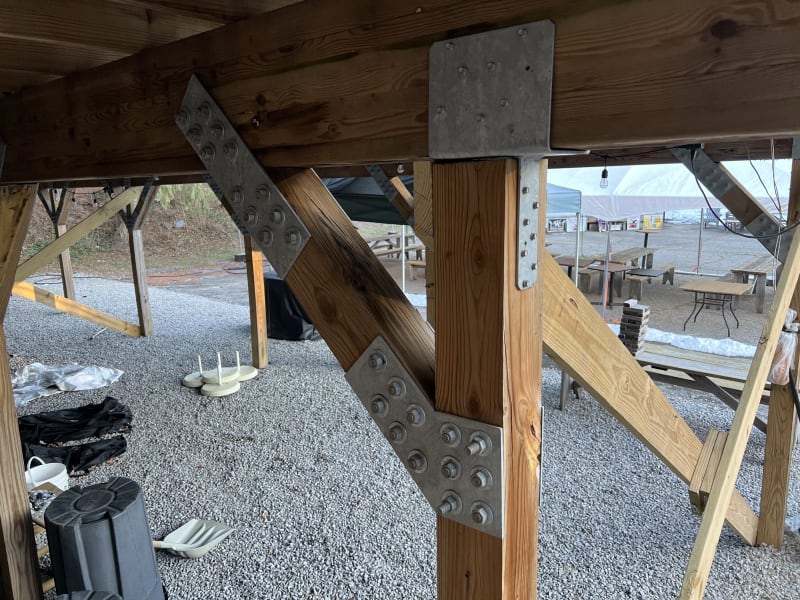
To answer OP's original question: I agree with the comments above that these are custom fabricated pieces.
Now, to go off on a tangent:
While this knee-brace connection is certainly better than many that I've seen in the wild, the connection as a whole makes little sense from an engineering perspective. Here's why:
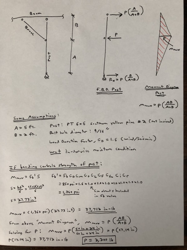
I think it's reasonable to assume that the weak link of the overall connection will be the post failing in bending, or to be more exact, failing in combined bending and axial stress (although I'm going to ignore the axial part in making my point). Based on that assumption, in the calculations below, the maximum horizontal force acting on the post from the knee-brace is found to be about 2,200 lbs.
Considering that the post cannot support a horizontal load from the brace greater than 2,200 lbs, there's no point in creating a connection capable of resisting a greater force. If the brace is assumed to be at a 45 degree angle, then the corresponding tension force in the brace will be sqrt(2) * 2,200 lbs = 3,100 lbs (approx.).
Based on using what appears from the picture to be two 1/4" thick steel plates along both sides with 1/2" diameter bolts and browsing Table 12G of NDS 2018, it looks like it should be possible to resist the 3,100 lbs tension force with only 1 or 2 bolts, not 6! But suppose we wanted to use these connectors anyway, is there any problem with that? In terms of following the NDS code, the various spacing and edge distance requirements (that OP mentions above) of Section 12.5 need to be met. Although it's hard to tell from the picture, it appears that the minimum required edge distance of 4D (per Table 12.5.1C) is not being met for the post where the left most bolts are seemingly less than 2" (or 4D) from the loaded edge.
To dissect this further, the connection at the top of the post which appears to be a Simpson ECCQ66SDS, will need to resist a horizontal load from the top of the post into the beam. From the assumptions and calculations shown above, this force is equal to: P*(A / A+B), which in our case works out to be about 1,570 lbs. Can the connector resist that load? Maybe. Without getting into the number too deep, I think the 1/4" wood screws along both sides into the beam can probably resist this. I'm not as sure, though, if the resulting bearing force pushing on the vertical tabs from the post would be adequate. It's interesting to note that Simpson doesn't seem to provide any values for this connector loaded this way, so that could be the answer.
To fully analyze this connection, the combined effect of bending and axial force should be looked at, which will result in less capacity than indicated above. Other failure modes should also be looked at, such as shear, accounting for the reduced section per NDS Section 3.4.3.3, etc. Wood connection design (per code) is really complicated.
Feel free to critique this assessment if I'm overlooking something.