Continue to Site

Eng-Tips is the largest engineering community on the Internet

Intelligent Work Forums for Engineering Professionals

  • Congratulations cowski on being selected by the Eng-Tips community for having the most helpful posts in the forums last week. Way to Go!

Post installed anchor/plate drilling 6

Status
Not open for further replies.

Pixy

Structural
Mar 22, 2022
84


HTSIlg.jpg


Who among you have tried drilling concrete pedestal with already base plate on top. That is. You will drill through the baseplate and concrete and even cut through any rebar inside (that is redundant anyway just believe me).

What is the cheapest rotary hammer wattage you could get for this? Let's assume there still space above to position the drill tool. That is why I need just compact and cheap one. The base plate has thickness of about 0.6". The rebars have either 0.78" or 0.39". Don't suggest extremely expensive gigantic drilling for oil exploration. It's just for rare one time use. I couldn't hire any tool.

Also the above anchors can be inserted into the baseplate, concrete base, right? or is there no anchor bolt that can be used with baseplate already in place?
 
Replies continue below

Recommended for you

If it was only shear parallel with the moment frames, you could add square tubes, bolted to u/s of the rafter, with vertical caps plate and epoxy-doweled anchors to face of column, sufficiently below the top of column that you engage the adequately reinforced concrete column. Not a particularly elegant solution.

FRAME_wlpqsq.png


With only a "tin roof" how are you distributing the seismic loads through your roof system? Is there roof bracing?
 
There were no braces in the roof. In the original structural plan. The seismic load are entirely resisted by the cast in bolts and post installed anchors. But since the contractor didn't insert the post installed anchors. Masonry walls were not used to avoid more inertial or seismic load.

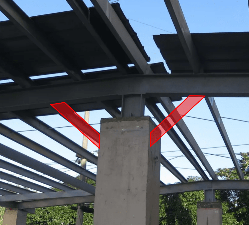
Now client wants masonry walls put up. So since it is not possible to drill holes through baseplate and concrete on top. Shear cap would be installed instead like the following.

zUtC1u.jpg


There will be 2 pcs of 5/8" Hilti bolts on each side (avoiding the failure cones of each). So each column will be designed to resist 68 kips of lateral load from the rafter and masonry walls. To avoid more axial load. The masonry walls will be put under the I-beam, not extended above.

Have you seen a steel cap over column before? What you make of it if the side anchors can resist the shear from normal top I-beam moment and seismic shear?
 
rzafRw.jpg


9flEkG.jpg


The first picture is the top of the column before the 0.63" thick baseplate was put just above it.

The 2nd picture were the 12 pcs of 0.787" rebars without stirrups (on record).

Worse case scenario would be to chip portion of the column (imagine half of the wide) and put a concrete beam to support top portion of the masonry walls (to be put just to protect the neighbor concrete wall). But this would be expensive and time consuming. And the challenge of concrete beam would be to develop the beam rebars to make it an integral beam-column joint.

But first. Please give your actual experiences in side mounted baseplates. Please show photos of any side baseplates. Haven't you seen any?
 
dik said:
REINFORCING TO BE LOCATED PRIOR TO INSTALLATION. DO NOT CUT REBAR.

I would suggest adding by non-destructive methods language to the note. Don't ask me why I add to all my details. [banghead]
 
Is this just a light 'tin' roof? And your LFRS is cantilevered concrete columns? Looking at the pics above, I don't see where 68 kips of seismic load per column could possibly come from? I'd double check loads before coming up with a fix. I don't see how that framing can deliver any load to the column parallel to the ridge? The little stub column would just fall over. Are you sure you have the LFRS and load path correct?

Why can't you just add the 2 extra anchor rods? The hole is already in the baseplate right? Just stick a drill in the hole and drill it out, clean it, fill it with epoxy, and shove the rod in. That's all there is to it (kinda). If there's no hole in the baseplate, drill a hole in it.

Also be weary of the tops of the columns. See the dark grey 'cap' on the far column of the photo of the framing? That looks like grout that they poured after they realized they poured the column too short. That's like...6" of grout with probably no steel in it.
 
Is that darker gray thing at the top, a metal baseplate the size of the column? If so, can you weld a BAR to the baseplate going down the face of the column and not secure it to the face of the column. The strut will not, likely, be a compression member.

Rather than think climate change and the corona virus as science, think of it as the wrath of God. Do you feel any better?

-Dik
 
Is that darker gray thing at the top, a metal baseplate the size of the column? If so, can you weld a BAR to the baseplate going down the face of the column and not secure it to the face of the column. The strut will not, likely, be a compression member.

Yes the metal baseplate is in same size of the column. Why would one weld a bar to the baseplate going down the face of the column and not secure it. what would be purpose of the bar?
 
Is this just a light 'tin' roof? And your LFRS is cantilevered concrete columns? Looking at the pics above, I don't see where 68 kips of seismic load per column could possibly come from? I'd double check loads before coming up with a fix. I don't see how that framing can deliver any load to the column parallel to the ridge? The little stub column would just fall over. Are you sure you have the LFRS and load path correct?

Why can't you just add the 2 extra anchor rods? The hole is already in the baseplate right? Just stick a drill in the hole and drill it out, clean it, fill it with epoxy, and shove the rod in. That's all there is to it (kinda). If there's no hole in the baseplate, drill a hole in it.

Also be weary of the tops of the columns. See the dark grey 'cap' on the far column of the photo of the framing? That looks like grout that they poured after they realized they poured the column too short. That's like...6" of grout with probably no steel in it.

Before the non shrink group was injected beneath the baseplate. They have to put forms to is so there is only an inlet where the non shink group will be pumped. So the dark grey cap is marks after removing the form. It's only in the surface.

About 68 kips in each column. The 68 kips is not the seismic load. It is simply the resistances of the column when additional anchors at sides inserted. This 68 kips resistance will just to make sure the masonry wall to be put at the perimeter will be anchored at the top, and they won't just fall over with the I-beam at top supporting the masonry walls not just topped over. Remember during seismic. Half of the wall will want to fly to the sky (or simply uplift). It is the post anchors in the columns that will make sure it doesn't happen.
 
Another idea. Someone here actually suggested to cut the baseplate, add post anchored bolts and reweld the baseplate.

How easy it is to cut with metal grinder a 0.63" thick baseplate?


KGF4Mh.jpg


After it is cut at middle. We will put 0.78" Hilti anchors (shown in blue) that is distant 8 inches from edge with capacity each of about 14 kips shear or times 2 = 28 kips total shear capacity). If this is not enough. We will put side baseplates to create shear capacity per column of more than 50 kips. There are 9 columns so capacity would be 450 kips. This would be enough to secure the top support of the masonry walls and rafter for thin metal roof. But how easy or hard to cut a 0.63" thick baseplate?
 

The load in the diagonal strut will likely be compression only. This means the BAR going down will be tension only and any load the BAR places on the column will be compression only. Why do you need to secure the BAR to the column? [ponder]

Rather than think climate change and the corona virus as science, think of it as the wrath of God. Do you feel any better?

-Dik
 

Because of uplift.

Imagine a seismic wave going upward from ground. It can lift the rafter and roof upward. This can put all the existing bolts in tension and possibly yield them until they reach tensile strength (breaking the bolt).

Also because of the masonry walls that will be put up. The perimeter top i-beam will have more momentum with half wall going up or create more uplift.

So why shouldn't the bar or better yet side baseplate be attached to the sides with 2 anchor bolts at middle (at required space between them vertically) to avoid any concrete breakout at edge?
 
Thanks... didn't know there was uplift.

Rather than think climate change and the corona virus as science, think of it as the wrath of God. Do you feel any better?

-Dik
 
Pixy, if u hv ur masonry walls along the periphery, then how does seismic shear from that masonry walls get transferred from the steel columns to the RC column by anchor connection. How do the steel columns get this shear dependent on masonry weight?

I knew the seismic shear comes from the weight supported above such as ur thin roof, purlin, self-weight of roof frames etc.
 

Thanks... didn't know there was uplift.

In your opinion, angle bar or side baseplate welded like a cap is stronger in shear than any anchor at middle? And imagine the side baseplates are 19 inches square shape. Even if there is uplift, and the original top anchors all have yielded or even broken. The displacement of the uplift would be less than 19 inches so the welded steel cap would just bounce up and down the column shaft and still not fall out due to the cap? What do you think?
 

Pixy, if u hv ur masonry walls along the periphery, then how does seismic shear from that masonry walls get transferred from the steel columns to the RC column by anchor connection. How do the steel columns get this shear dependent on masonry weight?

I knew the seismic shear comes from the weight supported above such as ur thin roof, purlin, self-weight of roof frames etc.

E4XHEE.jpg


See photo above. Did you see the I-beam at the top?

We will remove the studs with hardiflex cladding and put masonry wall just below the I-beam.

Now imagine the vertical rebars of the masonry wall connected to the bottom of the I-beam on top of column. This would give more momentum to the I-beam during lateral movement. So this would cause more shear to the baseplate connected on top of the column. What do you think? Are you thinking the masonry blocks weight have no bearing on the momentum of the vertical rebars welded to bottom of the i-beam (which is welded to baseplate and bolted to concrete)?

Oh. In the photo. We tried to drill holes to put the 0.63" HIlti anchor bolts but we only got 2 holes that are 5 inches deep, rest are 3 inches or 2 inches. I wonder if the epoxy grout you inserted in post installed anchors can bring back the strength of the holes. In other words, the strain of the epoxy grout is closed to concrete and not like soft epoxy that is very strain incompatible with concrete.
 
Are u considering full seismic shear from masonry to go to the steel beam and subsequently to the baseplate? You could consider half of it going to the baseplate and the rest half to the bottom of the wall.
 

Even half of it would be heavy. The wall height to the top I-beam is 9.8 feet. Half of height would be 4.9 feet. Or masonry wall about 0.2156 kip per foot. Since the wall between columns span 19.68 feet. Half of it would be about 10 feet x 0.2156 kip per foot or 2.156 kips.

And if the floor keeps accelerating. The 2.156 will increase to 21 kips or more as seismic energy is added to the dead weight of the wall. What you think?

Hmm.... Just welding all 4 side baseplates to make a steel cap without any side anchors would be strong for shear? If there is no significant moment on top that can make the original top anchors yield, isn't it?
 
How does this 2.2 kips dead weight becomes 21 kips when earthquake occurs. is ur design spectral acceleration 10 times of g? I think it can hardly be higher than 23% in worst cases. So 23% of 2.2 is 0.51 kips shear.

What am i missing?
Your column cap should work to transfer the shear force as bearing pressure to the concrete column, as I understand.
 

Last month my mentor asked me to consider energy from shelling. He asked where would the energy go.

Oh, another thing. He always used 4" concrete hollow blocks in exterior wall in all his designs and construction projects. He said as long as the top support is competent. 4" CHB would be fine to lessen seismic load.
What do you think about 4" CHB for exterior wall as long as top support is competent? Because some are using double the thickness.
 
Shelling? As in warfare, artillery shells landing and exploding near the building? I would advise you to not do that. Designing a building as a bomb shelter or hardening an existing one is a complicated and very expensive process. Unless this is meant to be a local shelter, it's not worth it. Besides...how is that lightweight roof going to deliver that load? I think your load path will break down before it gets there.

And no, 4" unreinforced masonry is generally no good for exterior walls. For single story I'd consider 6" reinforced, 8" minimum for unreinforced. It's easy to check - you apply out of plane seismic and wind loads to the wall and compare the stresses to the allowable levels listed in the code. I only show 4" for interior, non-load bearing walls or supported veneer.
 
Status
Not open for further replies.

Part and Inventory Search

Sponsor