jszymkowski
Automotive
- Dec 27, 2002
- 14
Looking for some suggestions...
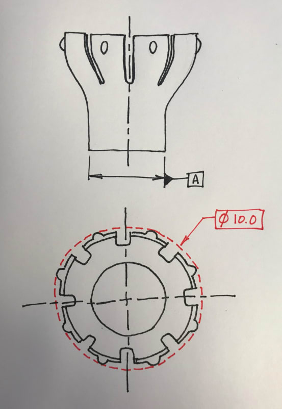
I am having difficulty defining the positional tolerance of features in a circular array. In the attached illustration (first angle projection), the tangent point of each bump to the red diameter must lie in a tolerance zone defined by two cylinders 0.2 apart centered on datum axis A. I need to define this using ISO GPS rules.
Indicating the measured points must be taken at a tangency, seems to be the roadblock for me, but perhaps there is a better way to define this.