Continue to Site

Eng-Tips is the largest engineering community on the Internet

Intelligent Work Forums for Engineering Professionals

  • Congratulations cowski on being selected by the Eng-Tips community for having the most helpful posts in the forums last week. Way to Go!

Please suggest reading materials for designing gusseted plates for moment transfers

Status
Not open for further replies.

P1ENG

Structural
Aug 25, 2010
237
I have a square HSS column that receives moment at the cap plate connected to a W beam. The column is also fixed at the base for anchoring to the foundation. I will start with a fact that I have reviewed AISC Design Guide 1 and (per its recommendation) I would prefer to eliminate the gussets by making the plates thicker. This is all well and good for the base plate because I have a large surface to connect to with any number and pattern of anchor bolts I could use.

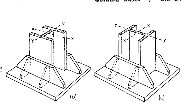
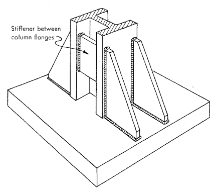
However, IF I wanted to design a gusseted base plate, are there any design materials out there that I could read? There are several configurations of gussets that I can think of: triangular gussets coming straight off each corner of the tube (like a swastika), (2) sets of triangular gussets on each face of the tube, or (2) gussets on each corner. Any guidance on how to analyze the anchors, gussets, yield lines of the base plate, etc.?

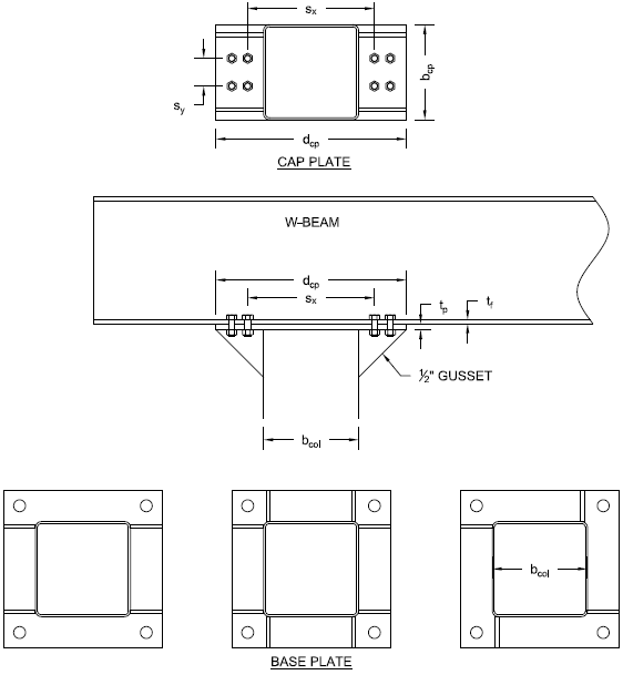
At the cap plate, I am more limited because I can only connect to the width of beam. Also, the prying action on the W-beam flange requires an unrealistic thickness. I need multiple rows of bolts to transfer the moment. I am aware of AISC DG16 but this is for W beams. Any suggestions on adapting this for HSS? With multiple rows of bolts I also need to figure out how to consider prying action (due to the thickness of cap plate and/or flange thickness of the W beam) as well as checking the W-beam flanges for required stiffeners. Specifically, when you have multiple rows of bolts with different tensions and are checking the previous prying/flange conditions, do the bolts get checked individually or do they influence each other?

I appreciate anyone that can point me in the right direction. My google search for gusseted baseplate design led to many results that reference IS800 (Indian Standard 800). My jurisdiction is the U.S.

Juston Fluckey, SE, PE, AWS CWI
Engineering Consultant
 
Replies continue below

Recommended for you

Unidirectional moments?

I like to debate structural engineering theory -- a lot. If I challenge you on something, know that I'm doing so because I respect your opinion enough to either change it or adopt it.
 
Apologies, no. Single-axis bending only.

Juston Fluckey, SE, PE, AWS CWI
Engineering Consultant
 
OP said:
Any guidance on how to analyze the anchors, gussets, yield lines of the base plate, etc.?

My goto source is Blodgett's Design of Steel Structures. There must be something more current available out there but I don't know of it. A few clips below. I think that the simplest stiffened arrangemtn, if it can be made to work, are the two bracket plates that straddle the section. Design seems to be a first principles thing including:

1) Base plate designed for the stiffened condition.
2) Welds designed to transfer required forces.
3) Stiffeners designed to transmit compression without local plate buckling, bending, or shear failure.

That's pretty generic, I know. Like I said, everything that I've seen has been pretty first principles-ish.

OP said:
Specifically, when you have multiple rows of bolts with different tensions and are checking the previous prying/flange conditions, do the bolts get checked individually or do they influence each other?

It would depend on the bolt spacing and geometry. Compounding interaction is certainly conceivable. For serious moments, connecting to the side of the HSS column with wrap around continuity plates might yield better results.

Capture1_zocdl8.png

Capture2_t28nrg.png


I like to debate structural engineering theory -- a lot. If I challenge you on something, know that I'm doing so because I respect your opinion enough to either change it or adopt it.
 
Koot,

As always, thank you. I was finding only that type of gusset configuration when doing my searching. I did some drawings showing what the cap plate and (3) base plate options would look like. Please see below. I will doing some traveling for the next couple days so I won't be able to check in here, but please keep the discussion going. If we can only discuss one option for each, it would be the cap plate above and the base plate in the middle below.

And to clarify, I could do some thinking and come up with a method of analysis that would suit me, but if there are any questions from the AHJ I would prefer to point to a published design method. At the least, even this thread's documentation would be helpful if there was a consensus on the method of analysis.
Capture_ia40aw.png


Juston Fluckey, SE, PE, AWS CWI
Engineering Consultant
 
Definitive no on the 3rd option for me. It would induce torsion into the column. Maybe a trivial amount, but it just doesn't look all pretty and symmetrical to me.

Why would you need the extra stiffeners shown in option 2 if it's just single axis moment resistance required?
 
The structure is analyzed in both directions independently. So while there is bi-axial bending, it does not act concurrently. The majority of bending will be in one direction though. I don't care for the third option either. I don't know that my client has ever used this configuration, but I found its drawing in a review set of old calculations for them. There wasn't much documentation on the old calculations that I have and it is in Excel, so I haven't been able to decipher the analysis method they used for that option.

I know they do use the middle base plate option. Regardless of whether the gusset is actually needed, the gussets will remain because the shop has been doing it that way for several years and that is what they are used to. Sometimes extra labor is justified by not confusing or retraining your shop. I'm ok with that, but I will not put the gussets in my calculations if I can show that it works without them. But in the one offset, cantilevered condition, I am finding that I do need gussets at the cap plate.

Juston Fluckey, SE, PE, AWS CWI
Engineering Consultant
 
I've used the following paper for several years now: "Design Aid for Triangular Bracket Plates Using AISC Specifications". It was published in the 3rd Quarter 2008 AISC Engineering Journal.
 
Unless you have an RBM (really big moment), I try to avoid all the gusset plates; it's generally less costly to go to a thicker base or crown plate. Should, however, have beam web stiffener plates over the column.

Dik
 
pvchabot, thank you. I will look for that paper.

dik, I agree that I would go thicker if I could to eliminate the gussets. However, why do I need beam web stiffeners over the column? I check web local yielding and web crippling and neither check shows that I need stiffeners. The flange on the other hand does need something as the calculated minimum (not the minimum to assume no prying, but the absolute minimum) thickness required by my prying action is not met.

Juston Fluckey, SE, PE, AWS CWI
Engineering Consultant
 
I do it out of force of habit... also, I'm a strong believer in designing beams to accommodate the design moment, thereabouts. Having the plate stiffener helps insure that in an overload condition, the beam maintains its elastic/plastic cross-section for post-elastic strength.

Rather than concern myself with the stability of the cross-section, it's less costly for me to add the stiffener plate.

Dik
 
With regard to the beam-column connection, what are the parameters that can be played with here? Is this an existing thing that you want to leave alone or can we mess with geometry and stiffeners etc?

In the current configuration, it's hard to see how you'd address the prying issue without making some changes such as:

1) Add some stiffeners to improve the prying effect. The improvement may be minor and difficult to asses.

2) Add some more bolts and spread them out so that you're engaging more flange in the prying action.

3) Use a sort of washer plate above the flange to stiffen the system against prying.

While I doubt AHJ would call you out on it, the stiffness of the connection is the part of this that would bother me most, more than the strength. Tough to evaluate that. The strength we can cobble together with first principle stuff to a large degree.


I like to debate structural engineering theory -- a lot. If I challenge you on something, know that I'm doing so because I respect your opinion enough to either change it or adopt it.
 
dik,
Someone else mentioned designing the connection for a minimum of 1/2 the design capacity of the beam. I asked where this requirement came from, but he was unsure. He said a local forced him to do it a long time ago. Do you have any knowledge on where this type of requirement came from? This structure is not part of a building structure. It is a canopy: single column with a beam that forms a T-shape (moment transfer at the beam/column only during unbalanced roof loads).

KootK,
It is only existing in the sense that I don't think the shop has ever installed gussets on the W-beam. Because the gussets are going to be there regardless of their need, I am not concerned with the defining or calculating the stiffness of the connection. I will just assume the gussets give me any required stiffness. Over the weekend, I have addressed some of my concerns and am able to continue my calculations without the "need" of gusset plates (again, they will be there because it is a shop standard). I consider the (4) bolt pattern on each side of the column, but ignore the gussets still (like the originally preferred method). I assume my moment about the center of the column with compression on the column sidewall and triangular tension pattern on the bolts (i.e. farthest set of bolts from compression column sidewall receives largest tension). AISC already addresses prying action when multiple bolts would influence each other which I missed earlier (the tributary 'p' has an upper bound equal to the bolt spacing). So prying action on my wide flange was a piece of cake. For the prying action of the cap plate, I conservatively assumed the sum of all forces acting 100% either on the pair of bolts farthest or closest from the face of the column; worst-case results control the thickness and prying force factor.
1) I check both the beam flange and the cap plate for prying. I can increase the cap plate thickness, but I can't increase the flange thickness. I can only add bolts to spread out the load to more of the flange, which I did. Adding more bolts means I need a stiffer cap plate to get the load to the bolts farthest from face of the column.
2) See item 1
3) I saw this done in another example but couldn't figure out how long they made the plate washer. It was a thesis and I didn't have the time to delve into the math and it was stated that the washer plate only helped under certain conditions because the W-beam has several hinge points in it's bending profile while the plate washer only addresses the portion of the web outside of the hinge points. If I need this method in the future, I will give this option some more thought.

Thanks again everyone for the help.

Juston Fluckey, SE, PE, AWS CWI
Engineering Consultant
 
I don't design for half the capacity, and not familiar with this design (requirement?). Beam moments can be quite high and designing for half of the moment can be unreasonable IMHO.

Dik
 
Status
Not open for further replies.

Part and Inventory Search

Sponsor