Hi All,
Many thanks for your responses.
I think I should have explained what this part actually does and what the critical features on it are.
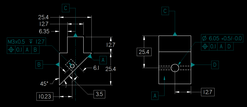
So its a block, the real critical features are the 2x dia .201/.197 holes in section x-x. Two photodetectors are fitted into these and their alignment to each other is pretty critical.
The M6 holes in this view are for a plastic grub screw to block off the hole left by drilling the holes mentioned previously.
The M12 holes are for a cable glad to fit into and the 10.5mm hole x 2.3 deep is for a piece of 2 core cable to go into this is soldered onto the photodetectors before they are fitted.
The .205/.197 holes in the top centre view are mounting holes so their position is not overly critical either.
AndrewTT:
I have incorporated your points 1 & 2- basic mistakes on my part.
Sorry I should have explained the function of my part- Do you think your points 3 & 4 are required based on this.
AXYM:
I have added centre lines and changed the note to 2x tapping drill .
Because they are only for a cable to go through the position relative to the cross holes is not overly critical.
Sorry I should have explained the function of my part up front
mkcski:
Projection is 3rd angle. The reason the M12 holes arent in the ISO view is because they are on the bottom face.
I agree reference the problem establishing which face is the datum. How do I get around this? Do you mean physically engrave the datum on the part or change the design in such a way that it is not symmetrical?
chez311:
This is the standard font in NX. I believe it is unique to it.
pylfrm:
-I have added a note to the view in D7 stating that it is an auxillary view to show the position of the laser engraving only. This part is anodised and is laser engraved after this.
-With regards to the ambiguity of the datum surfaces- I see this is a problem but I can't rely on the laser engraving to indentify these, this problem was also addressed by mkcski. Do you have any ideas how I get around this- make the part non symmetric or marking the surface to denote them
-There is a general note in the drawing border to cover non basic dimensions
-I have removed the 10.50mm dimension and replaced it with the words tapping drill
-BS3642 should have been BS3643- sloppy mistake on my part.
I have removed the specification and changed the call out as to how Y14.5 calls threads out.
Latest version of the drawing attached- thanks guys, I appreciate everyone taking the time to help me out here.
![[wink]](/data/assets/smilies/wink.gif "[wink] [wink]") ) are for mounting then you should be looking at the floating faster formula or fixed faster formula (appendix B), as appropriate, to select the required position tolerance. Also, you may need to use compound position to refine the orientation error of these holes for proper function.
) are for mounting then you should be looking at the floating faster formula or fixed faster formula (appendix B), as appropriate, to select the required position tolerance. Also, you may need to use compound position to refine the orientation error of these holes for proper function.