Continue to Site

Eng-Tips is the largest engineering community on the Internet

Intelligent Work Forums for Engineering Professionals

  • Congratulations cowski on being selected by the Eng-Tips community for having the most helpful posts in the forums last week. Way to Go!

PIPE FITTING TO SELECT

Status
Not open for further replies.

shamnas

Mechanical
May 14, 2015
15
Dears,

I have pipe API 5L Gr.70 , so,
which pipe fitting specification use for this ( tee , elbows spec)

This is to construct a tank capacity of 261 m3 . The pressure inside is 90 bar (temp = 60 degree Celsius).

my pipe thickness is 15.9 is this withstand the pressure .


Replies continue below

Recommended for you

Pipe size needed.

Are you creating a "tank" from pipe?

Normally you will need F70 grade fittings if the same size as the pipe.

Remember - More details = better answers
Also: If you get a response it's polite to respond to it.
 
pipe size = 40 inches

pipe placing parallel and 1.5 meter distance

for connecting pipe i have to use elbow or 180 degree bend

in my design pipe is reduced at the bend so can you please suggest the reducer size ,


For buffer storage tanks, we use same calculation wall thickness as per ASME b 31.3 , so as per my calculation its 30 mm thick . its too high for 40 inch.
 

shamnas,
It would help if you sent a sketch of what you are trying to do?

Sometimes its possible to do all the right things and still get bad results
 
Your attachments don't load. Please upload using the box at the bottom of the posting box.

Also what design code and what fluid?, liquid or gas?


Remember - More details = better answers
Also: If you get a response it's polite to respond to it.
 
It looks like an exchanger (40"?).
Why a safety on the exchanger?
Design pressure? design temp? What fluid? what cooling/heating fluid?
 
Design Pressure = 90 bar
Design Temp = 60 degree celcius
Fluid = Natural Gas ( Fuel Gas )
Inside Storage we have maintain 60 degree Celsius, so there is a trace heating

This is a storage Tank(capacity 261 m3). when the system shutdown from storage tank it will supply gas to Plant.

 
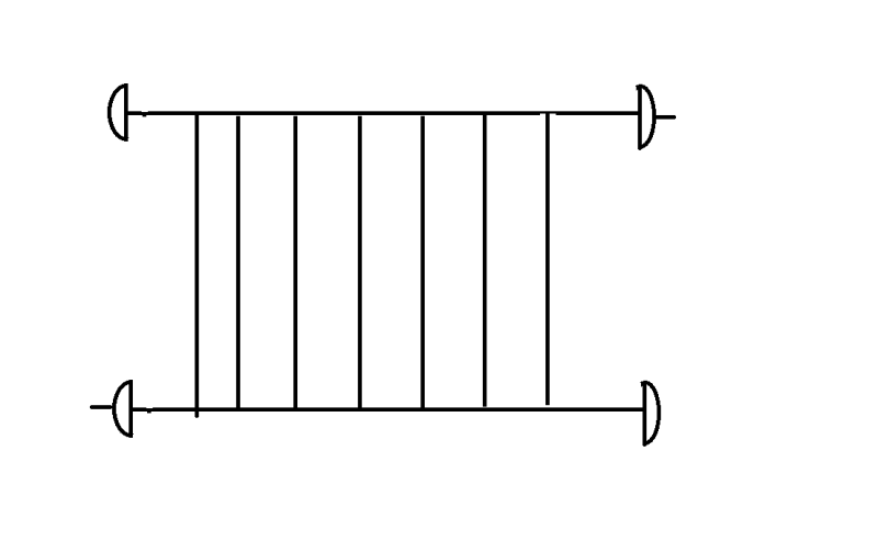
I assume you are using pipe either because you have surplus pipe available or because you think it's less expensive than a pressure vessel? Your design conditions fall within a class 600 system. Basically, your system reminds me somewhat of a finger style slug catcher although I realize this is to store gas, not remove liquids.

< in my design pipe is reduced at the bend so can you please suggest the reducer size >

That depends on how much flow this system has to supply to the plant. The gas flows from the outlet to the plant and for the upstream segments, the gas has to travel through the various return bends. A quick hydraulic calculation should give you an idea what you are looking at. Remember as you supply gas to the plant and the pressure drops, the pressure drop across the bends as the gas is expanding and flowing out is going to increase, I don't know what your lower operating pressure range is.

< Inside Storage we have maintain 60 degree Celsius, so there is a trace heating >

Why? Is that the expected dewpoint of the gas? That's a lot of pipe to heat trace and insulate at an additional cost. If it's a dewpoint issue, why not let the liquids condense and be drained off as needed?


Thanks a lot ,

In my design i put a main line then coneecting by a tee,

drw_dqcyvy.png
 
Dears,

What is the maximum velocity flow through a HDPE pipe ?

For CS pipe 20 m/s is the limit !
 
There is no "maximum" velocity for either steel or PE pipe. 20m/sec is a recommended limit, but I've seen 40m/sec for clean gas for steel. All depends on what you're transporting, the amount of hard materials in it and what sort of fittings you have and whether the flow is continuous over a long period or occasional at that velocity.

High velocities of gas >20m/sec are normally to be avoided if you can as the pressure drop becomes very high per unit length and you risk erosion over time at bends, tees, elbows etc.

Remember - More details = better answers
Also: If you get a response it's polite to respond to it.
 
There are a few crucial issues that remain unresolved so far, which to me appear to be :

a) What design code should be used for this pipe assembly to reduce wall thickness: is it B31.1, or B31.3 or B31.8 ? Is there a justification for using B31.1 -which is meant for power plant piping.
b) Why is this pipe assembly heat traced : Is it because the depressure profile during supply mode shows a low temp which is beyond the min temp limit for the downstream user? Heat tracing wont help here, you've got to add on a heater to maintain the min temp required - also keeping the pipe assembly above ground helps a bit, but hardly.
c) Current plan is to use API 5L Gr 70 : - is this good for the MDMT or lower design temp assigned for this assembly - we cannot take credit for heat tracing for this reason either. Given this is a complicated pipe assembly to simulate for the purposes of deriving min metal temp, an appropriate simulation program should be used ( not the standard version of Hysis or Pro II or similar).
 
Status
Not open for further replies.

Part and Inventory Search

Sponsor