Tek-Tips is the largest IT community on the Internet today!

Members share and learn making Tek-Tips Forums the best source of peer-reviewed technical information on the Internet!

  • Congratulations TugboatEng on being selected by the Eng-Tips community for having the most helpful posts in the forums last week. Way to Go!

pipe elbow FEA

Status
Not open for further replies.

kszyho100

Mechanical
Joined
Oct 27, 2004
Messages
18
Location
PL
Hi

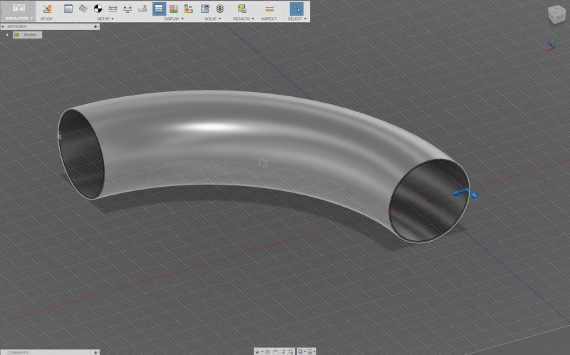
I want to check stress in carbon steel elbow (this is preinsulated underground hot water pipeline). I know all forces (axial, transverse, moment) but don't know where to put them.
Should the elbow at one end should be constrained and on the other one I should put loads?

Thanks in advance.
 
i recommend tell more about the loads and what you are trying to do
 
Some additional explanation. I did calculations and I have following results.
expansion
expansion_apurk9.jpg

axial forces
axial_forces_we9lx3.jpg

transverse forces
transvers_forces_vxvqzu.jpg

moments
moments_knzfmz.jpg


Than I calculated stress by von Mises formula and now I want to compare it to FEA.
I tried Autodesk Fusion 360 but I have problem how to put forces. One bend end is constrained
bend_DN200_dw7pzy.jpg

moment is working onZ-X plane.
 
I would add sufficient straight length of pipe to both ends of the elbow to avoid artificial constraints - such as a restriction on ovalization. A minimum length would be 10 sqrt(r*t), but for that size, I would use 10D. Then, fix one end and apply your moment to the other end.
 
Status
Not open for further replies.

Part and Inventory Search

Sponsor

Back
Top