Continue to Site

Eng-Tips is the largest engineering community on the Internet

Intelligent Work Forums for Engineering Professionals

  • Congratulations cowski on being selected by the Eng-Tips community for having the most helpful posts in the forums last week. Way to Go!

Pipe diameter change 3

Status
Not open for further replies.

Jack Nicholson

Chemical
Oct 20, 2016
119
Hi.
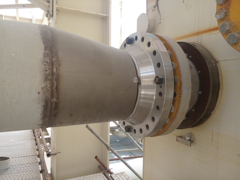
In inlet and outlet pipe nozzles we have diameter reduction or enlargement. Why?
For example picture of outlet nozzle of multistream heat exchanger have been attached. Why?
IMG_20170510_110052_sg1kk3.jpg
 
Replies continue below

Recommended for you

The pump discharge nozzle size is a function of the design of the pump.

The suction nozzle is generally sized one size larger than the discharge nozzle. Some exceptions are noted for specific types of other pumps such as solids-handling pumps where the suction nozzle size is made the same size as the discharge nozzle so that particles that enter the pump can also exit the pump. This assumes that the impeller design in that pump will also pass the same particle size.

The reducer on the inlet side of a pump ensures that the fluid velocity in the suction line is slowed sufficiently to provide a smooth flow of liquid with minimized friction losses in the piping to ensure as high as possible the NPSH available from the system.

The increaser on the discharge side of the pump is designed to increase the pipe diameter from the pump nozzle to reduce the fluid velocity in the discharge piping in order to reduce the total head the pump is required to pump against.
 
Hosein,
For anyone who is trained, experienced and familiar with process plant Piping it is quite normal and quite simple.
A The Vessel Nozzle and the joining Flanges (on the right) are one size maybe 18" NPS.
B The pipe (on the left) is another slightly larger size maybe 24" NPS.
C The Reducer (in the center) is how we join the two different sizes together.

Why are you questioning the Design?

Sometimes its possible to do all the right things and still get bad results
 
Inlet and exit nozzle sizes for vessels and heat exchangers are usually based on some approach to an upper limit on rho-v2. For shell and tube HX, see TEMA design books for inlet and exit nozzle size rho-v2 limits for various applications.

While in plant piping line sizes are based on generalised pressure drop limits or velocity limits(in most cases). Noise limits may also apply to continously operating high velocity flare lines.
 
Why are you asking, as pennpiper has already asked.
As to why, well this is what the pipe engineers specified.

It is a capital mistake to theorise before one has data. Insensibly one begins to twist facts to suit theories, instead of theories to suit facts. (Sherlock Holmes - A Scandal in Bohemia.)
 
Quoted "While in plant piping line sizes are based on generalised pressure drop limits or velocity limits(in most cases). Noise limits may also apply to continously operating high velocity flare lines.".
I'm searching for this type of answer. I think there are lots of philosophy beyond this design.
 
Quite simple. Think about it. Nothing more than this. If you need a pump that has a capacity of 100 L/m, one that operates at 3600 rpm would be one half the size of a pump operating at 1800 rpm. One half the size usually means very much cheaper equipment and by using the smaller equipment, you can have a smaller plant. But faster velocity, high speed machines, pipe and equipment generally means higher pressure drops, bearing wear, lube oil consumpiton and the need for more maintenance. Design life usually is shorter as well.

The typical plant design problem: How to build a plant with the capacity I need as cheaply as possible that can operate for the longest design lifetime.

Solution:
If you can operate at a faster velocity, you can use smaller, usually cheaper, equipment. But pressure drop will be higher when the fluid has to travel through the small equipment and pipe size when moving at that faster velocity, so if you made all the pipe in the whole plant equally as small as the equipment, you wouldn't have enough pressure to get the fluid to the other side of the plant. The alternative to that is increasing the design pressure, which again would increase cost of designing equipment and pipe for the higher design pressure.

The optimum solution: How to design the lowest cost plant having the capacity I need depends on the cost of all the equipment and pipe. Equipment is very expensive and pipe is relatively cheap, so you can easily see that the best way to optimize the whole problem of designing a plant that uses expensive equipment and cheap pipe is to selecct the smallest, cheapest equipment, operating at the highest velocity and complement that by use of the largest pipes, operating at lower velocities and low pressure drops to keep total pressure loss across the plant to a minimum. That keeps the equipment costs low while larger diameter pipe, still having not so high pipe costs, give acceptable pressure losses.

Result: The plant is designed for required capacity, acceptably long design lifetime, runs at reasonable cost and has the smallest footprint. Optimized!

Technology is stealing American jobs. Stop visas for robots.
 
Not lots of philosophy, just correct engineering practice and knowledge applied to the design.

It is a capital mistake to theorise before one has data. Insensibly one begins to twist facts to suit theories, instead of theories to suit facts. (Sherlock Holmes - A Scandal in Bohemia.)
 
Plant design procedure. You ARE an engineer, right?
If you don't get that, you will never understand.
Do you think that equipment piping is smaller than plant piping because the fab shops can't buy bigger pipe??? No, there is an engineering design-cost optimization reason for it.

What part are you having trouble understanding?


Technology is stealing American jobs. Stop visas for robots.
 
For custom designed equipment, the engineer can make the nozzles whatever size they want. This doesn't mean it will be the size you want, right? For mass produced equipment, what you see is what you get. Then, there is equipment that is in between these two extremes. On a 13 inch impeller centrifugal pump we use, we can get either a 4" x 3" or 6" x 4". The choice is a matter of cost; the pump curves are nearly identical.

If the engineer can put a successful process together by wisely choosing the many pieces of equipment together, with their various sizes of nozzles, with pipe, valves, and fittings, then the engineer keeps his job/paycheck. If not, he doesn't. It is a highly personal optimization problem.

Good luck,
Latexman

To a ChE, the glass is always full - 1/2 air and 1/2 water.
 
"You ARE an engineer, right?"

You may have identified the problem.
 
I think so too. Maybe he's a chemIST, as in not A chemical engineer.

Technology is stealing American jobs. Stop visas for robots.
 
In two phase flow, line sizes should also be based on avoiding undesirable slug flow regime throughout the entire turndown range. If not, you can have thermal duty failure in heat exchangers or excessive liquid loads in vessels for example.

Sometimes, a separator drum is used to split out the vapor and liquid phases in a 2 phase feed to a HX and act as a surge vessel also, and the 2 separated phases are directed to individual passes in a multistream HX for example. There are many cases reported of multistream HX thermal failure resulting from slug flow 2 phase streams fed directly to the HX w/o an intermediate V/L separator drum.

What is the problem with the configuration in the photo ? You have us all guessing.
 
Problem?
I don't think there is any problem. He just wants to know why the equip nozzles are smaller than the plant piping.

Technology is stealing American jobs. Stop visas for robots.
 
Mr Biginch, I think you get me wrong!! If I'm being ungracious I apologize.

Not to brag, but I'm an engineer with descent eng-view. I know there's a reduction in pipe diameter, due to engineering consideration.

Quoted: "there is an engineering design-cost optimization reason for it."
I'm wondering what is that engineering design-cost optimization??

Look! I think we should consider lots of limitation:
1- corrosion limitation
2- pressure drop limitation.
3- Velocity limitation.
4- ...

Is there anybody show me how a desinger consider this limitation???
 
Well then put your engineering hat on.
The reasons you mention are the exact same that I told you above. Except for corrosion, which is unimportant in sizing considerations. Maybe you mean erosion, which might have an affect, if your fluid is heavy or dirty.

Technology is stealing American jobs. Stop visas for robots.
 
Well, I don't think you mention that!!! anyway, I put my hat on long time ago, dear!!!
 
Thank You for your expression of gratitude.

Technology is stealing American jobs. Stop visas for robots.
 
For me the first thing I would be considering is the best pump selection (in terms of pump hydraulic efficiency)for the flow required and the minimum total head across the pump/s. I would run some quick head loss calcs. with the discharge pipe at the same diameter as the discharge flange and review the numbers, if head was considered excessive I would go up a pipe size and repeat the exercise until such times I was satisfied the power costs / pipe costs were at an acceptable levels to each other. By the pipe sizes shown it would appear this is a largish pump and every point of hydraulic efficiency lost could run you into mega bucks over the years of operation.
It's not rocket science, it comes down to straight economics.

It is a capital mistake to theorise before one has data. Insensibly one begins to twist facts to suit theories, instead of theories to suit facts. (Sherlock Holmes - A Scandal in Bohemia.)
 
Status
Not open for further replies.

Part and Inventory Search

Sponsor