Continue to Site

Eng-Tips is the largest engineering community on the Internet

Intelligent Work Forums for Engineering Professionals

  • Congratulations cowski on being selected by the Eng-Tips community for having the most helpful posts in the forums last week. Way to Go!

Pin Bushing Sleeve Analysis 1

Status
Not open for further replies.

DoubleBoy

Mechanical
Apr 19, 2018
2
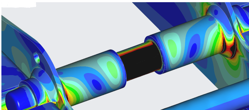
Hi, I've got a high load pin supported by two bushing sleeves. It's picture below for illustration of this. I'm wondering how one would go about calculating bending in the sleeves by hand. The pin is routed all the way through the bushings through the next wall so it isn't like the entire load is applied to the end of the sleeve, but due to the pin deflecting I know the load wouldn't be applied at the wall either. Is there a good way to approximate the load amount and location or do I just have to rely on the FEA?

Pin_m8e2uh.png
 
Replies continue below

Recommended for you

DoubleBoy,

What fun!

Does your FEA model take into account the stiffness of your pin?

Your pin approximately is a cantilever beam, fixed at one end and guided at the other. Your two bushings look like cantilevers fixed at one end and loaded at the opposite end. If this were my problem, I would work out the stiffness of everything under a nominal deflection.

--
JHG
 
Yes the model does consider both material's stiffness, and I trust it to a certain degree, but am just looking to verify. What I decided to try is using the fact that deflection for both components will be equal, and setting the FL3/3EI cantilevered beam deflection equations equal to each other. Then, solving for the ratio of the bending forces applied, I'm hoping I'm correct in thinking I can use that force ratio to find the bending force to apply to each "cantilevered beam" individually. I'm also cutting the whole pin/sleeve assembly in twain and ignoring the exposed portion of pin, applying the load at the end of the sleeve.

I'm making a few assumptions I don't love here, such as ignoring friction between two steel bodies and that the pin is cantilevered, but I don't need to be perfect I think.

Someone call me out if I'm bein crazy.
 
DoubleBoy,

From Roark's (7th ed), for a guided cantilever, ymax = WL3/12EI. That ignores the effect of your two bushings.

--
JHG
 
You don't even need to do it by hand. The thin plate supports where the bushings are connected (welded/brazed?) look to be flimsy (probably a very good thing) enough that they won't support the bending of the bushings. The stresses that you see are due to contact, not bending. The vertical plates deflect easily under very little load at the end of the bushing, so if you want to do it by hand, consider the pin as being simply supported at each end. But you don't need to do it by hand. If you must, the sleeves will simply go along for the ride in regards to whatever deflection you have on the pin.

Unless there are gussets on the bushing and plate that I don't see. I reserve the right to change my mind if the side plates have good stiffness from something outside of the image.

EDIT:
Where I said:

"The stresses that you see are due to contact, not bending."
This was wrong. The stress is caused by the sleeve deflection (and bending at the connection to the side plate), but sleeve itself does not have any appreciable means of resisting the deflection of the pin. Assume that the pin is simply supported in the centers of the side plates.

Engineering is not the science behind building. It is the science behind not building.
 
Status
Not open for further replies.

Part and Inventory Search

Sponsor