Continue to Site

Eng-Tips is the largest engineering community on the Internet

Intelligent Work Forums for Engineering Professionals

  • Congratulations waross on being selected by the Eng-Tips community for having the most helpful posts in the forums last week. Way to Go!

Perpendicularity FCF view placement best practice

Status
Not open for further replies.

sendithard

Industrial
Aug 26, 2021
186
This drawing I came across recently had me thinking about best practices. The perpendicularity FCF is tied to datum C, but datum C is shown on the front view. Is is better practice to place this FCF on the same view that the datum is being created?

Capture_siaaju.jpg
 
Replies continue below

Recommended for you

Datum features aren't "created", they are identified. If that feature has some constraint, as by a FCF, then it is better to have the Datum Feature Symbol next to the FCF, but it's not entirely necessary. A person using the drawing should examine the entire drawing, every nook and cranny, to see what's what, particularly for a tolerance analysis.
 
I was under the assumption that the 'datum feature' is the actual part surface in reality that you can physically touch. I thought the 'datum' is a virtual plane that is created from the datum feature of a theoretically perfect part. With what you see on the drawing would you have placed this FCF in the front view?
 
Did I mention "datum"? Where did "datum" enter into this?

Where is datum feature B?
 
With descriptive and projective geometry we were taught that a line between them was a 'folding line' and the image should reflect what would be seen if viewed from that perspective.

Rather than think climate change and the corona virus as science, think of it as the wrath of God. Feel any better?

-Dik
 
D,

In no way shape or form am I arguing with you. I'm a dumb newbie to gd&t and am honestly humbled just to get replies from you all.

To answer your question, I never mentioned 'datum features' on my original post. I only used the term 'datum'. You then replied saying 'datum features' are not created, they are identified. I was speaking of only datum C being pointed to. I am not sure if the proper term for the creation of datum C is it being 'identified' or 'created'. I just wanted to make you aware that I used the term 'datum' not 'datum feature'.

Below is the full drawing. I am curious if you don't mind if you would move the FCF to the front view and if not why not? Much appreciate as always....btw....I believe that datum B is the vitual centerline plane created. This drawing confused me at first b/c datum B and D seem to be the same until I read somewhere that a datum line colinear to the dimension line means centerline plane.

2_hlb6d7.jpg
 
Drafting is out of my league... just my $.02...

Rather than think climate change and the corona virus as science, think of it as the wrath of God. Feel any better?

-Dik
 
Clipboard01_mtsllj.jpg


Rather than think climate change and the corona virus as science, think of it as the wrath of God. Feel any better?

-Dik
 
The arrow points to a datum feature. It's a datum feature symbol.

The rest is preference.

Whatever that part is for - it's weird. With no idea what that part is for, it's not worth analyzing what it's like now, but it looks like someone is just following some rules that haven't much to do with the function of the part. Is this a real part or is it from a workbook test?
 
I thought FCF pointed to theoretical perfect planes(ie datums) and not 'datum features'. Are those arrows in my original post pointing to 'datum features' or 'datums'?

 
Strangely nobody asked this question so far: show me Perpendicularity tied to datum "C"

"For every expert there is an equal and opposite expert"
Arthur C. Clarke Profiles of the future

 
sendithard,

We can't have datums without physical datum features. You must identify and tolerance your datum features, from which your theoretical datums are derived. Actually as per the standard your datums are "a theoretically exact point, axis, line, plane, or combination thereof derived from the theoretical datum feature simulator" in Y14.5-2009 or "derived from the True Geometric Counterpart" in 2018. So your datum features determine the geometry/location/orientation and behavior of your datum feature simulators/TGC from which your datums are derived. In practice which really matters is your datum features, their associated simulator/TGC, and the interaction between them - the theoretical "datums" are merely a consequence thereof, hence why as 3DDave suggests they are "just an idea in your head". And hence why whenever the subject comes up and theres discussion of whether a datum feature/simulator/TGC establishes a point/plane/line or combination thereof my response is typically "who cares? whats your simulator/TGC look like? whats its behavior and how many DOF does it constrain and how?"

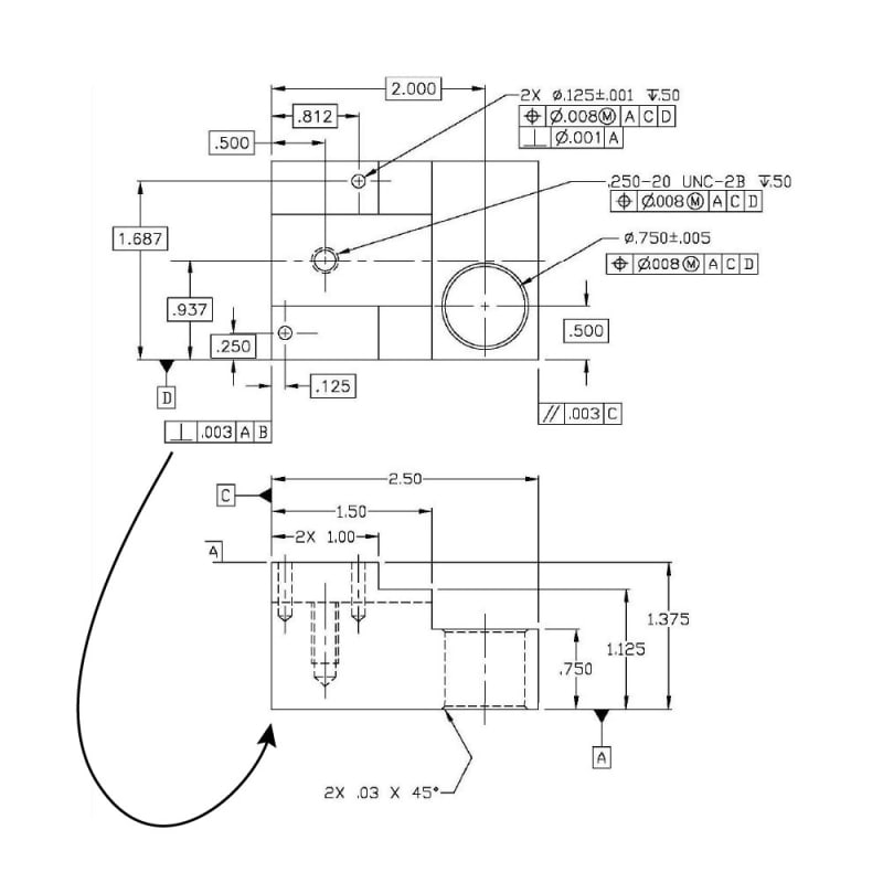
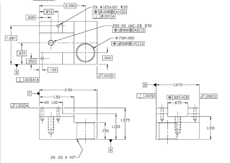
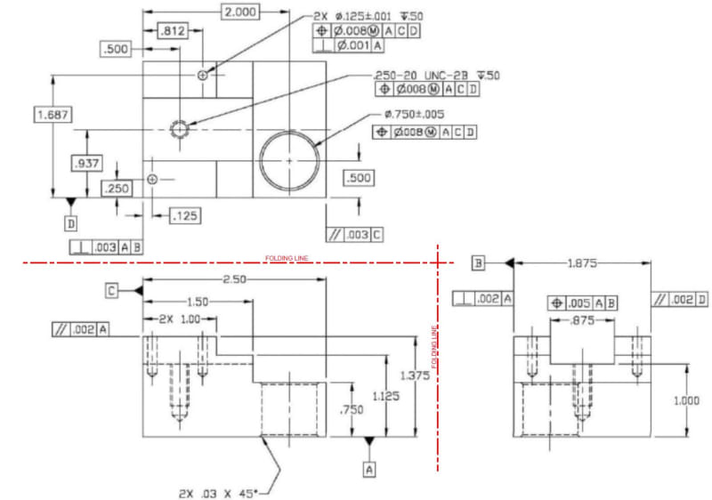
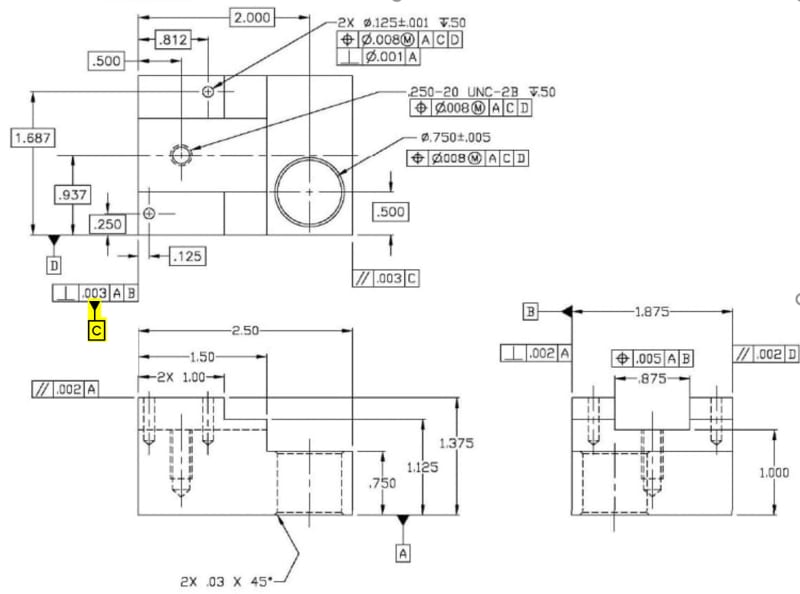
Anywho - to your original question, the view in which you apply your FCF rarely matters (I think theres a few special cases in which it does) as long as its clear what feature(s) it applies to. If theres something which improves readability/comprehension of the drawing its usually a good idea, but rarely required. The exception in your case is the application of the chamfer dimension on hidden lines, this I believe is not allowed or at least not recommended - all the examples in the standard are shown in section views, though I can't remember if its explicitly stated.
 
Thanks chez and 3d. I learned a lot with this simple question. Appreciate your time in the replies.
 
sendithard

If I understand your question correctly, I will hang up the datum C sumbol directly under the FCF as highlighted on the figure below.

2021-10-08_214020_g0sk9b.jpg


Season
 
Sure, and also move datum feature symbol [D] as well, to the view on the right.

Also it's conventional to put the FCF under the size dimension.
The parallelism to [A} should say 2X; note that it doesn't create a continuous feature.
The surface for datum feature [A} is not necessarily flat; all others have a geometric characteristic controlling their form.
 
sendithard,

You are asking about best practises, not the actual interpretation drafting standards.

Good drafting is like good writing. Connected pieces of information ought to be located close together. Datum features[ ]A and[ ]B, datum feature[ ]C and its perpendicularity are called up on three different views. I don't see a way to do this in less than two views, but the GD&T boxes can be moved closer together. I have seen much worse than this.

Are you the drafter, or the manufacturing guy trying to make sense of the drawings? If the latter, consider charging your customer more to account for the extra time needed to interpret the drawings.

--
JHG
 
Status
Not open for further replies.

Part and Inventory Search

Sponsor