Tek-Tips is the largest IT community on the Internet today!

Members share and learn making Tek-Tips Forums the best source of peer-reviewed technical information on the Internet!

  • Congratulations TugboatEng on being selected by the Eng-Tips community for having the most helpful posts in the forums last week. Way to Go!

PDF Line thickness from drawing

  • Thread starter Thread starter 1ne_SHOt
  • Start date Start date
1

1ne_SHOt

Guest
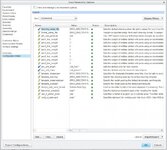
I am having trouble with the lines on a PDF after they are exported from a drawing to PDF. When exporting all lines seem to be of an appropriate size with the exception of the entity lines. They are so large that you cannot see the detail of the part itself. I have browsed through some similar topics that have come up here throughout the years and have found to do a couple things but it didnt fix my problem. I am using Creo 2.0 and here is what I have set in the configuration options of the drawing:

pdf_use_pentable yes
use_8_plotter_pens yes
pen1_line_weight 1
pen2_line_weight 1
pen3_line_weight 1
pen4_line_weight 1
pen5_line_weight 1
pen6_line_weight 1
pen7_line_weight 1
pen8_line_weight 1

Doing these tweaks has no impact on the exported pdf, if anyone has some suggestions that would be much appreciated.
 

Attachments

  • Config Editor 2.jpg
    Config Editor 2.jpg
    87.6 KB · Views: 61
first you have to create your own pen table file --> pen_table.pnt

inside insert following:

pen 1 thickness 0.05 cm
pen 2 thickness 0.05 cm
pen 3 thickness 0.05 cm
pen 4 thickness 0.05 cm
pen 5 thickness 0.05 cm
pen 6 thickness 0.05 cm
pen 7 thickness 0.05 cm
pen 8 thickness 0.05 cm
 
This actually worked. I put a file called "table.pnt" into my working directory and it instantly worked. Only one problem though, the lines on the entity are the same pen as the border lines. Is there any way to keep the borders as thick as they were before while making all the lines on the parts thin?
 
Yes, you need to create a .pnt file. You then need to add a path in your config.pro file so it will read this file (pen_table_file). I have attached my pen table file which also shows you what pens are used for each entity color.
 

Attachments

Sorry its been a while since I posted back. So here is where I am. I have been using an intermediate line thickness that works to some degree for the part entity lines and border lines since they both are controlled by pen 1. In an attempt to make pen 4 control the borders it says that the color should be red. So what I have done is open up the .frm file and highlight each of the border colors and make them red. Keep in mind that all tables and text on this .frm file are blue. When I try to print to pdf to see what i get, all blue text turns to black(which is what I want) and the red lines from the border are still red. It even says when I make them red that they are controlled by pen 4. I am just wondering why the blue lines and text ended up black(as desired) and the red lines ended up in red.
 

Part and Inventory Search

Sponsor

Back
Top