Tek-Tips is the largest IT community on the Internet today!

Members share and learn making Tek-Tips Forums the best source of peer-reviewed technical information on the Internet!

  • Congratulations TugboatEng on being selected by the Eng-Tips community for having the most helpful posts in the forums last week. Way to Go!

PCB with multiple identical instances - ISO drawing- 2

Status
Not open for further replies.

Kedu

Mechanical
Joined
May 9, 2017
Messages
193
Location
US
i_-_Copy_denged.jpg


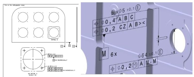
I am working on a part similar to the one shown with model based definition geometrical controls. The part’s product definition should be based on the ISO GPS (8015, 1101 and 14405-1)
The center hole is considered as a datum feature for the 6 small holes. I have 24 of those instances (24 inside diameters which each have 6 small holes) across the PCB (circuit board). ASME (left picture) offers an elegant solution by using the “Individually” tool.

My question is how to accomplish the same thing in ISO?

P.S. Our current MBD (as shown in the right picture) is currently wrong and is to be updated based on my description above (change datum system to the centering inside diameter hole). The center hole to be located to A|B|C| and become the "individual" datum for those 6 small holes.
 
Interesting question, I don't know the answer, but there are a lot of very knowledgeable and educated ISO guys on this forum.
You might want to use a note and identify the datum hole and then position of the adjacent holes to the datum hole (again maybe with the note saying something like “each pattern of six holes relative to its applicable / corresponding datum feature”)


Kedu,

I am not sure that ISO currently has an equivalent of the INDIVIDUALLY notation when applied to datum features, but I would definitely like to hear other opinions on that.

Having said that, if this was my drawing, I would do the following:

In the main view:
-- Specify size and position for the large holes: 6x ø79.4 +/-0.1; |POS|ø1.4(M)|A|B|C|.
-- Specify size and position for the small holes: 24x ø3.6 +/-0.1; |POS|ø1.4(M)|A|B|C|.

In the detail view:
-- Modify the view label to 6X DETAIL A INDIVIDUALLY.
-- Associate datum feature D symbol to the large hole.
-- Specify position for the small holes: 4x (ø3.6 +/-0.1); |POS|ø0.4 CZ (M)|A|D(M)|. (I believe the reference dimension for the diameter could be skipped as well).
 
ISO 5458:2018 paragraph 5.4.5 (Rule E: indication of multi-level single indicator pattern specification) has something to offer here.
Not sure how to apply to your requirement.
 
ISO is using new CZ - SZ notation to indicate "pattern of patterns".

Didn't have a chance to get all the way thru.

"For every expert there is an equal and opposite expert"
Arthur C. Clarke Profiles of the future

 
 https://files.engineering.com/getfile.aspx?folder=7c490180-997b-45f2-83d6-41782f04f76a&file=Capture.PNG
CH,

Where your excerpt is from? Could you, please, provide the source?

CZ_SZ_-_Copy_gxrbqf.jpg
 
CH,
Thank you very much for the reference.
I suspected it is not from an ISO GPS standard and it is based on someone's (author’s) personal opinion and his/her best judgement. I am saying this because CZ SZ (in this order) combination, as shown in your figure, is meaningless according to ISO 5458:2018. The correct combination shall be SZ CZ, again according to the standard.
So sometimes those articles, pictures, figures, statements we have to take them with a grain of salt.
 
Regardless of whether the example provided by CH is correct per ISO 5458 or not, I am afraid it is of no use in Kedu's case because of each of the larger holes needing to be referenced as an individual datum feature for each corresponding group of 6 smaller holes.
 
Status
Not open for further replies.

Part and Inventory Search

Sponsor

Back
Top