Eng-Tips is the largest forum for Engineering Professionals on the Internet.

Members share and learn making Eng-Tips Forums the best source of engineering information on the Internet!

  • Congratulations dmapguru on being selected by the Eng-Tips community for having the most helpful posts in the forums last week. Way to Go!

Partially Connected Column & Punching Shear 2

Status
Not open for further replies.

Trenno

Structural
Joined
Feb 5, 2014
Messages
831
Location
AU
Hi all,

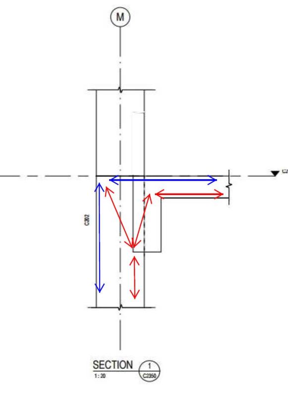
I'm trying to find ways of making the below detail work.

I'm using AS3600 currently, but am definitely open to other code's justification. I know we are pretty conservative when it comes to punching shear.

At this stage the Arch. is aiming for "X" to be 200mm, however I can only seem to squeeze 400kN punching shear capacity out of the configuration below.

Does anyone have any suggestions or point me towards material that can help me justify the smallest possible "X" dimension?

Thanks

XDLswIp.png


"Shibby right..."
 
When they do this in all precast systems in my area, the "structural column" is the narrower bit throughout the entire length and the ledge bit is basically treated as a full length corbel.

Regarding your new punching shear case, this is pretty much exactly the case that I presented above: wide beam on narrow column. This is an excellent paper on the subject Link.

You've got a few choices:

1) Punching shear
2) The sketch that I posted above.
3) Run your stirrups through the joint and deliver some of the shear around the side of the beam. This is basically a poor mans STM model and does require a tie into your column or some moment in the slab to resist torsion in the beam.

The third option is the one that I see the most. Note that it is really an alternate means of handling two way shear even if it presents like a one way solution. I can provide some details if you're interested in pursuing this.

I like to debate structural engineering theory -- a lot. If I challenge you on something, know that I'm doing so because I respect your opinion enough to either change it or adopt it.
 
I see no reason to consider punching shear as you are incorporating a beam to carry the load in one way action. I would prefer more bearing into the column. It was 200 before, why the change? And I agree with rapt, the whole thing needs to be well tied together, which is a problem with most precast elements.
 
I would use U bar into the column rather than cogged top and bottom bars. Much better development.

I doubt with a connection of 140 that you can get all of the reinforcing bars in where you need them. There will have to be corner bars for the slab bars and they will have to be inside the column bars, while the column ties are outside the column bars providing an effective development between them.

50 cover + 24mm column bar + 24mm corner + 24mm slab bar = 122 + at least 24mm and preferably 40 cover to the slab bars + tolerance for placement of corner bars in the bends does not add up.

Go back to 200mm connection!
 
I've been asked by my manager to design this connection using STM. Having very little experience in this method of design, please bear with me.

Below is my first attempt at the strut/tie configuration. I have a vertical shear and a clockwise moment. I'm assuming the vertical shear will be at the beam's centreline and the strut forming from the slab, which is just the resolved couple force from the moment.

Is STM the best way to push forward for this connection?

Feedback is most welcome - I'm sure KootK would be chomping at the bit to help out.

STM_First_Pass_uiatf5.jpg
 
And yes, it's all RC now. No more precast (for the time being...).

 
Sweet! Unfortunately -- but awesomely -- I'm in Jamaica right now which will slow me down some due to a lack of scanner access and a decent data plan. But we shall persevere!

1) Will you have a roof version of this? That would be the worst case and is more or less what you've presented in your STM. You'd have some other options at a floor only joint.

2) At the joint, I believe that the moment should be represented differently as it will come into the beam continuously along the beams length.

3) I think that STM a good approach. Simpler methods of checking bearing and development length would just be incomplete versions of the same thing.

I like to debate structural engineering theory -- a lot. If I challenge you on something, know that I'm doing so because I respect your opinion enough to either change it or adopt it.
 
I drew this as though the beam concrete wasn't there but, obviously, it would be. The model assumes that the column ties would continue full depth throughout the beam depth. It simplifies the model but I'm not sure how practical it is.
image_ligaza.jpg


I like to debate structural engineering theory -- a lot. If I challenge you on something, know that I'm doing so because I respect your opinion enough to either change it or adopt it.
 
KootK, common on, you are in Jamaica...what is with the red marker pen and white paper sketch. A photo of a sketch done on the beach in the sand with piece of drift wood is more appropriate :-)

Enjoy Jamaica. I do recall my wife and I in 1990 (before kids) doing the snow-bird trip to Jamaica to get away from the winter blues of Toronto.

Trenno - sorry to hijack your thread. Back to normal programming.
 
Yes, I can only imagine how many of my resort cohorts were also doing STM models at the bar between scuba lessons. I am what I am.

The only non-canned thing that I'm doing this trip is that I've hired a guy to drive me from Momtego Bay to the mean streets of Kingston and back. I can go pretty much any place that I want in between in a 12 hr period. I'm game for suggestions if you've got 'em Ingenuity.

I like to debate structural engineering theory -- a lot. If I challenge you on something, know that I'm doing so because I respect your opinion enough to either change it or adopt it.
 
Status
Not open for further replies.

Part and Inventory Search

Sponsor

Back
Top