Continue to Site

Eng-Tips is the largest engineering community on the Internet

Intelligent Work Forums for Engineering Professionals

  • Congratulations 3DDave on being selected by the Eng-Tips community for having the most helpful posts in the forums last week. Way to Go!

Partial Moment Release of Connection

Status
Not open for further replies.

LeonhardEuler

Structural
Jun 19, 2017
200
All,

Have a theory question about connection design and flexibility of connections.

A connection was originally designed as a full moment connection, but FEM results came back and the connecting elements were not strong enough to carry the full end moment. The connection however is flexible and could be consider a partially restrained moment connection. The current idea is to replace the connection in the structural analysis program with a small member with an I equal to the connecting element and determine the new moment reaction at the node in question. This is done and the moment is lower and the FEM results show the connection passes. This is all good and seems to be allowable; however, I am having a little trouble with some of the theory behind this.

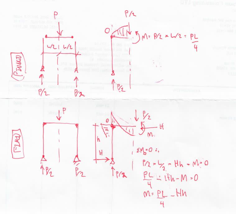
My main problem is that this is a "cantilever" connection which is being partially released about the vertical axis. I understand that a partial moment connection results in greater moment in the connecting member, but I feel that the force applied to the connecting beam must eventually make it into the column line, through the connecting element, so how can it have less of an internal moment? How is that "extra" force being transferred. Perhaps it is due to the connecting members stiffness and that it stops rotating past a certain angle and transmits remaining force as internal shear in the connecting element. I have found it extremely challenging to put my question into words, but hopefully someone will have success in explaining this to me. Thank you.
 
Replies continue below

Recommended for you

BTW if it helps to orient those that may comment. The connection in question and the member connected to it are connected to an identical connection/member via a rigid diaphragm "deck plate" that sits atop the members, so some global moment is transferred through a force couple; however, when these were modeled as rigid links and full moment connections the moments in each connection were too high. I would be very happy if someone could make this theory make sense to me.
 
Even if theres a textbook that I could read that could help explain this would help
 
LeonhardEuler,

It is very hard to visualize what you are describing. A screen shot from your structural analysis program, a sketch, detail from a drawing, something visual to help wrap my head around your problem would really help formulate a response.

But the shortest answer I can give you is the basics don't lie.
If your hand calcs tell you there has to be a certain moment at a node due to force at a distance, it must be so.
You can get into more detailed modeling and accounting for structural action from attached appurtenance structure & blah blah blah, but if your primary structure is overstressed then it needs to be larger. Period.

You cannot make the problem fit the solution, that just killed a bunch of people in Florida.
 
LeonhardEuler:
If I understand your question correctly, you can’t do what you are proposing or trying to do, because your structure/beam has no place for the moment redistribution to take place; no place for the sloughed off moment’s carrying cap’y. to transferred to. A sketch would certainly help, but I think you are talking about a cantilevered beam which is over stressed at the fixed end, and can you make that work by your proposed method? You can’t. The beam starts to yield, starts to form a plastic hinge which grows, becomes a mechanism, and the rotation at the hinge becomes uncontrolled. The beam fails, it just more or less folds/hinges down. What you need to do is add t&b cover plates from the column out onto your beam far enough to make the needed moment work. These cover pls. might be CJP welded to the column using the beam flanges as back-up bars, then the pls. are fillet welded to the beam flanges. Think..., adding cover pls. to a simple beam, and if you cut this beam at its center line, that cut line is the face of your column flange.

The classic/std. example problem which starts to explain this moment redistribution issue, we used to call this “Plastic Design in Steel,” is a uniformly loaded, fixed-fixed beam. The two fixed end moments are wL2/12 and the center line moment is wL2/24. Given a WF beam, at some load ‘w,’ the two fixed end moments will start to cause yielding, and the formation of plastic hinges. At this point, these two moment regions can’t really carry much more load in bending, except as the hinge grows a little, they are at their plastic moment (Mp), but as long as they can carry the shear and they don’t buckle during hinge formation, the hinge can continue to develop, and the beam will carry more load, as the center line moment grows from wL2/24 to wL2/12. This new (imaginary?) beam has end moments of Mp and a center line moment of wL2/24, and can carry more load. In effect, it is like superimposing a simple beam, uniform load, with a center line moment of another wL2/24 on the above new beam. And, now you will have a total center line moment of wL2/12, the Mp for that beam section. This third hinge makes the original beam a mechanism, and this is a failure, uncontrolled rotations and deflections.

Take a look at some good, older, Steel Design texts, approx. vintage 1970, or the AISC Manual, about 7th Ed. or earlier. Good steel design texts should have a chapter on plastic design of steel, which matches my comments above and goes much deeper.
 
I think that I see what you're getting at. For illustration purposes, consider a frame consisting of one beam, two supporting columns, and a vertical point load at beam mid-span. We'll look at it with both pinned and fully fixed beam to column connections.

- Conservation of vertical forces for both systems is apparent with respect to beam shears, column axial loads, and column base reactions.

- There is an eccentricity created by the offset between where the load is applied and where the load is ultimately resisted at the column bases. The moment that this eccentricity creates is conserved in both cases. It redistributes for different degrees of beam/column connection fixity, but is still conserved.

- Your case lies between these two extremes but the same logic still applies. Bending moment may redistribute from member to member, including connection elements, but it will remain conserved in the aggregate.

c01_liguls.jpg


I like to debate structural engineering theory -- a lot. If I challenge you on something, know that I'm doing so because I respect your opinion enough to either change it or adopt it.
 
Here's a plan view of the framing and connections. As you can see they are cantilevered. I initially had connecting elements as full moment restraint and modeled with rigid links. I changed the rigid links to plates with an equivalent I to the actual connecting hinges and it decreased the moment at the connecting nodes and I can't figure out why, because it seems that full moment needs to be resisted by a cantilever.
 
 http://files.engineering.com/getfile.aspx?folder=d087e1f1-2706-4759-9c07-827309d2acbe&file=1521405472088-1820938718.jpg
This is what I mean that it seems that each connection must take the full F*L moment regardless of connection flexibility, but sense it is a system connected by a diaphragm it is making the reduction possible. Hopefully this makes more sense. Thanks everyone for the help
 
 http://files.engineering.com/getfile.aspx?folder=26ebfc14-b9e0-4464-ac64-fea57081c6da&file=15214058494942035536100.jpg
Perhaps with reduced stiffness the extra moment is reconciled by an increase in axial forces in the force couples. I am still trying to visualize why allowing rotation at the connections would result in this, but perhaps someone can finish out my thought more eloquently.
 
 http://files.engineering.com/getfile.aspx?folder=20ad6820-e466-49aa-84a4-962410d75a7f&file=1521407835832-434172267.jpg
Yes the moment in question is about the vertical axis. I'm calling the deck plate a diaphragm
 
If the force is parallel to the diaphragm connecting your beams then I understand.

I can explain with two cases:

1) If your beams and column were infinity rigid and fully moment connected at the column, and the load P was evenly distributed over the ends of each beam, You would have only a shear and moment reaction at the base of each beam, no force normal to the column and your diaphragm would have zero load.

2) If your beams are pinned to your column with load P evenly distributed over the ends of each beam, you would have a shear and normal force and zero moment at each beam to column connection and your plate element would carry all of the force required to resist the applied moment in tension and compression across its diagonals to the base and tip of each beam. Think X-bracing.
This is assuming you are using a Linear-Iso plate element in you modeling connected only at the four corners of the element to the end joints of the beam on each side. If you are using a more detailed model then there will be significant shear across the element parallel to your beam elements.

So as you vary the moment restraint from infinity to zero the moment at the base of each beam will reduce as the plate element is allowed to carry more load and the forces normal to the column will increase as the "X-bracing" forces provided by your plate increase.
 
 http://files.engineering.com/getfile.aspx?folder=7b22709a-d2d6-402f-bc5d-64cc367eacb3&file=plate_reactions.jpg
Status
Not open for further replies.

Part and Inventory Search

Sponsor