KonstantinBG
Electrical
- Aug 28, 2019
- 6
Hi,
I have been trying to design my parking roof utilizing STAAD.PRO. I would like to ask some questions about stuff that amazed me, perhaps someone may help.
Let me tell you some words about the roof - basically the roof is a cantilever type (maybe some people call it trellis) having only one column to the ground foundation.
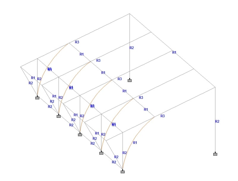
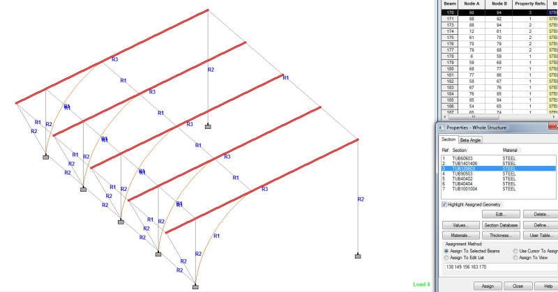
This is a picture of the roof structure in 3D.
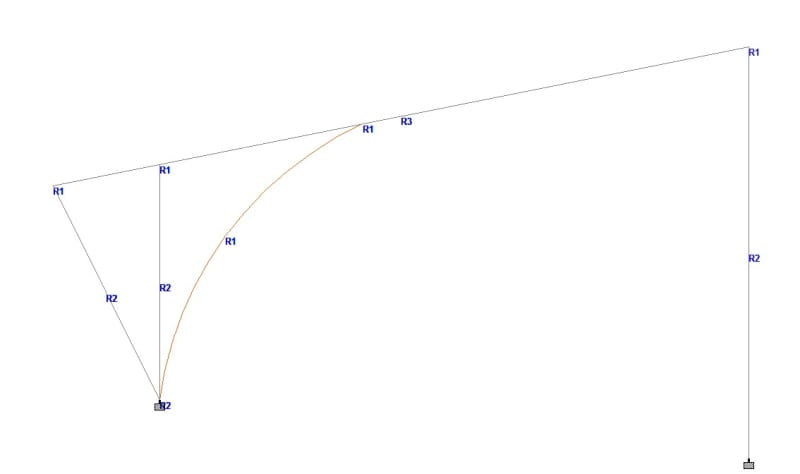
And a picture of the roof structure in 2D.
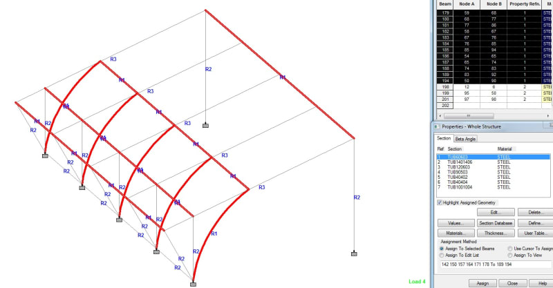
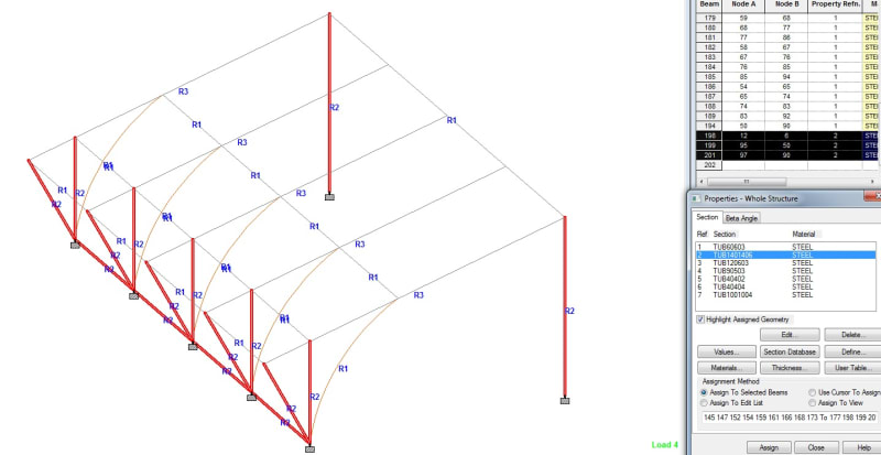
The next 3 pictures illustrate the sections that I chose. The sections marked in red are corresponding the highlighted section on the right side.
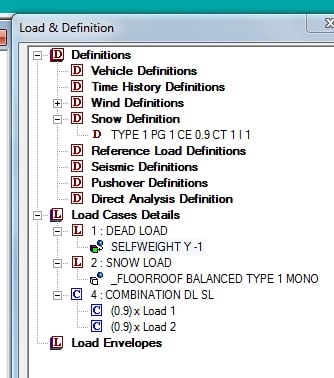
The next picture is the load definitions.
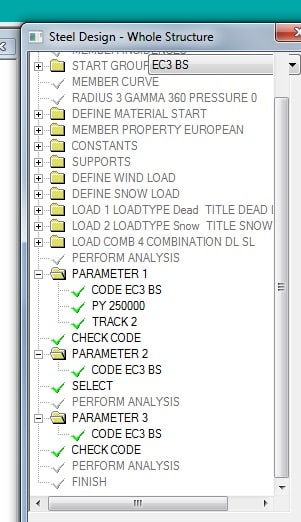
This is the Steel Deisgn Tab and the commands I defined.
Now my questions and the weird thing that amazed me.
In the output file the only beam that fails is the beam which is furthest away from the column or in other words the beam which is at the highest point of the roof. This makes sense and STAAD.PRO offers me another beam which is 120x60x3 mm compared with the prevoius - 60x60x3 mm.
Now, for the columnds I chose 140x140x6 mm beam. It does not fail but STAAD.PRO offers me a ridiculous beam - 40x40x2 mm. This is really weird for me.
What do you think does that make sense and should I trust STAAD.PRO or just use the beams I defined?
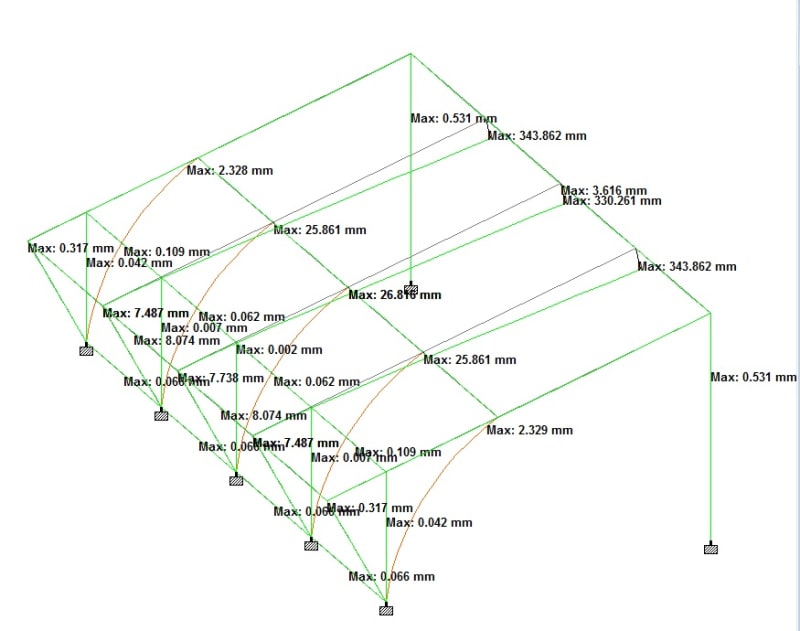
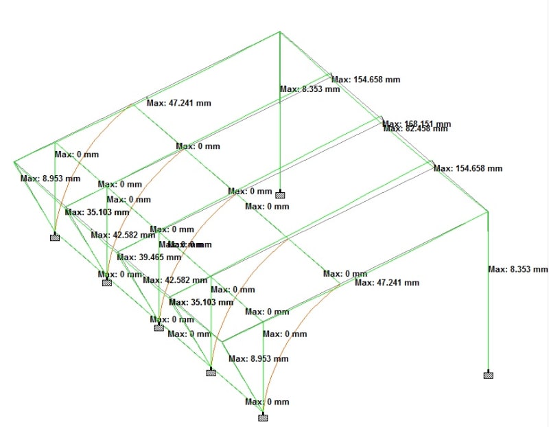
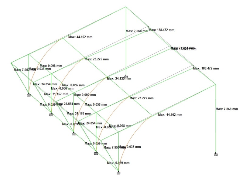
And perhaps you would like to see the Maximum Resultant Displacement diagram.
Maximum Displacement for DEAD Load.
Maximum Displacement for SNOW Load.
Maximum Displacement for Combination.
And another thing is that STAAD.PRO does not connect for some reason the roof beams(120x60x3 mm lie down on the column) to the beam at the highest point of the roof. I tried to divide the beam at the highest point but it just divides the beam into smaller beams in between the roof beams.
In conclusion I would like to know your opinion.
Am I doing the design correctly and is it going to be safe to build the roof?
I have been trying to design my parking roof utilizing STAAD.PRO. I would like to ask some questions about stuff that amazed me, perhaps someone may help.
Let me tell you some words about the roof - basically the roof is a cantilever type (maybe some people call it trellis) having only one column to the ground foundation.
This is a picture of the roof structure in 3D.
And a picture of the roof structure in 2D.
The next 3 pictures illustrate the sections that I chose. The sections marked in red are corresponding the highlighted section on the right side.
The next picture is the load definitions.
This is the Steel Deisgn Tab and the commands I defined.
Now my questions and the weird thing that amazed me.
In the output file the only beam that fails is the beam which is furthest away from the column or in other words the beam which is at the highest point of the roof. This makes sense and STAAD.PRO offers me another beam which is 120x60x3 mm compared with the prevoius - 60x60x3 mm.
Now, for the columnds I chose 140x140x6 mm beam. It does not fail but STAAD.PRO offers me a ridiculous beam - 40x40x2 mm. This is really weird for me.
What do you think does that make sense and should I trust STAAD.PRO or just use the beams I defined?
And perhaps you would like to see the Maximum Resultant Displacement diagram.
Maximum Displacement for DEAD Load.
Maximum Displacement for SNOW Load.
Maximum Displacement for Combination.
And another thing is that STAAD.PRO does not connect for some reason the roof beams(120x60x3 mm lie down on the column) to the beam at the highest point of the roof. I tried to divide the beam at the highest point but it just divides the beam into smaller beams in between the roof beams.
In conclusion I would like to know your opinion.
Am I doing the design correctly and is it going to be safe to build the roof?