Continue to Site

Eng-Tips is the largest engineering community on the Internet

Intelligent Work Forums for Engineering Professionals

  • Congratulations cowski on being selected by the Eng-Tips community for having the most helpful posts in the forums last week. Way to Go!

Parallelism across 3 surfaces meaning.

Status
Not open for further replies.

Inspector_Brent

Aerospace
Aug 25, 2020
2
Morning all,

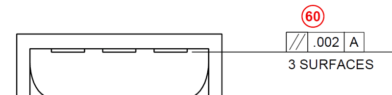
I wanted to get clarification from the experts on this, being that I don't have direct access to the Y14.5-1994 standard. We have a parallelism callout to 3 surfaces back to -A-, and there is debate in my department about whether this is meaning to treat the 3 surfaces as a single plane for this purpose, or if its a callout for each pad individually. My understanding would be that without the CF modifier, this callout would be for each pad on its own. Thanks in advance for your time.

3_Surfaces_Parallel_ttjspw.png
 
Replies continue below

Recommended for you

The CF modifier was added only in the 2009 revision of ASME Y14.5.
I conclude from your post that the relevant standard is the 94' version.
Either way, the specification as shown does not require coplanarity. For coplanarity control, profile tolerance specified for the 3 surfaces would be the correct requirement.
As shown, the tolerance can only apply for each surface separately when interpreting per the standard, but that is not necessarily the intent of the drawing maker. Unfortunately, there is a significant chance that the original intent was to impose a common tolerance zone. It is a common drawing mistake.
 
Inspector_Brent,

The continuous feature symbol was an addition for Y14.5-2009, it was not present in 1994. It has been further expanded in 2018.

While the intent may have been to create 3 coplanar tolerance zones I don't think that would be the default interpretation, even with the "3 surfaces" note. You would have to either add a clarifying note (while not strictly supported, a CONTINUOUS FEATURE note may get the point across) stating that they are to be coplanar or employ profile to enforce default coplanarity.
 
Thanks for the prompt replies, this is extremely helpful. Would this be the same interpretation if it was a flatness callout across the same surfaces?
 
chez311 said:
Parallelism is essentially flatness with an orientation requirement to the referenced datum(s)

When applied to surfaces.
 
While the intent may have been to create a single plane from the three surfaces, this doesn't do it. Parallelism does not locate features; not to a datum and not between features. All this does is ensure each individual surface is parallel to the datum, there is no coplanar control.

John Acosta, GDTP Senior Level
Manufacturing Engineering Tech
 
Y14.5-2009 says that "n SURFACES" designates a pattern when locational geometrical tolerance is applied to features.

1.3.42 Pattern
pattern: two or more features or features of size to which a locational geometric tolerance is applied and are grouped by one of the following methods: nX, n COAXIAL HOLES, ALL OVER, A ↔ B, n SURFACES, simultaneous requirements, or INDICATED.


Definition of Pattern in Y14.5-2018 changed to include profile tolerance.

3.44 PATTERN
pattern: two or more features to which a position or profile geometric tolerance is applied and that are grouped by one of the following methods: nX, n COAXIAL HOLES, ALL AROUND, ALL OVER, between A and B (A ↔ B), from A to B (A → B), n SURFACES, simultaneous requirements, or INDICATED, where n in these examples represents a number.


Could the next revision of Y14.5 include orientation tolerance in the definition of Pattern?
 
Woosang,

While not mentioned explicitly, profile was already included in 2009 as it is also a "locational" tolerance as it can control location. Hence the inclusion of "ALL OVER, A<->B" as these don't make much sense with position.

I'm not sure about next revisions and the inclusion of orientation only tolerances (perpendicularity/parallelism/angularity). From what I hear theres been some calls to include orientation tolerances in simultaneous requirements as well, I always thought their exclusion seemed a bit arbitrary.
 
Chez311,

You're right. The Standard has evolved to make ambiguous or controversial issues clear(though maybe not true for all). Including orientation tolerance to Pattern definition or not would be a different kind.
 
chez311 said:
From what I hear theres been some calls to include orientation tolerances in simultaneous requirements as well

How will it work with the principle that orientation tolerances do not locate and their datum references do not constrain translation? If there's a locating geometrical tolerance that references |A|B| for one feature and the same datum features are referenced in an orientation tolerance of another feature they will impose mutual location between the features, so I think we will not be able to say that datums referenced in orientation tolerances do not constrain location, will we?
 
Burunduk,

Simultaneous requirements for orientation tolerances would not impose a location requirement, it would only impose mutual orientation.
 
chez311,
On one part drawing there could be some controls applied on features or patterns referencing datums for position or profile, and other features or patterns having controls referencing the same DRF for orientation. Would this create a simultaneous requirement (pattern) in which some features or patterns are basically located to each other while other features or patterns are only oriented to them, and can float?
 
chez311,
That would surely be a very different type of simultaneous requirement, in comparison to what a simultaneous requirement means now. Might complicate things, I think.
 
Burunduk,

I don't see why. If it were explicitly included in the standard it might be wise to include additional verbiage as to how it might work with orientation for clarity, but theres plenty of people who believe this is already a legal use of simultaneous requirements - myself among them, albeit not necessarily by default but can be enforced by explicit use of a SIM REQ note. Anything else would violate the definition of orientation.

In fact, as you well know the very definition of simultaneous requirements states "no translation or rotation between the datum reference frames" therefore it does not create a pattern by locking the features in location/orientation to each other, but between their DRFs - hence why it could be applied to orientation. If an orientation tolerance of a certain DRF is not constrained to said DRF in translation by definition, then why would locking this DRF to another in translation/rotation change this? The orientation tolerance would still not be constrained in location - either to other features or its DRF, as doing so would violate its definition.

Some examples of support both on this forum and elsewhere, hopefully those on the forum don't mind me quoting them. You were actually part of that discussion as well.

From (
As for usage of SIM REQT, yes this is always an option, but we (chez311 and me) don't really see a reason as to why orientation tolerances could not be added to the simultaneous requirement rule by default.
Simultaneous requirement as the default is explicitly limited to position and profile, but I don't see anything stopping you from applying the "SIM REQT" notation to orientation tolerances.

From Paul Drake's Dimensioning and Tolerancing Handbook:
simreq_sbx1aa.png
 
I guess I always skimmed through the part of the simultaneous requirement paragraph that says "between the datum reference frames", and took it to mean that all position or profile controls on the same drawing that reference the same datum features in the same order of precedence & modifiers apply in the same datum reference frame simultaneously and the tolerance zones are basically constrained to each other directly. After all, that's generally how patterns are created and the standard specifies that a simultaneous requirement produces a pattern. Also in practice, a datum reference frame is associated with a specific inspection set-up and simultaneous requirements are inspected in the same inspection set-up. I guess I missed the idea of identical datum reference frames constrained to each other in all DOF. I'm aware that the location of DRF origin relative to the part is not always unambiguous (edit: in the sense that it can be located arbitrarily as long as it is fixed relative to the datum feature simulators) but for simple cases, there is definitely a default covered by the standard so it means that those identical DRFs should, or at the very least can be located at the same origin. Since they are also fully constrained to each other calling it two separate DRFs still makes little sense to me, but yes, I guess that could justify defining a common SIM REQT for orientation and location tolerances.
 
I guess I always skimmed through the part of the simultaneous requirement paragraph that says "between the datum reference frames"

Well thats the most important part. Its what makes the pattern creation mechanism different than any of the other grouping methods.

Also in practice, a datum reference frame is associated with a specific inspection set-up and simultaneous requirements are inspected in the same inspection set-up.

I agree. This could cause difficulties with hard/functional gauging (requiring floating pins and such) and would likely be an easier task for a tool like a CMM.

Since they are also fully constrained to each other calling it two separate DRFs still makes little sense to me

I don't want to try to over-analyze what the committee members may have been thinking, but it might be because the underlying assumption might be that every FCF establishes a DRF, even if those DRF's are identical/indistinguishable. This is instead of having one DRF when multiple FCF's are connected with a pattern creation mechanism (ie: SIM REQ) or multiple DRF's when they are separated (ie: SEP REQ). Maybe its just splitting hairs but it might be the best way to make sense of it. The difference may seem minuscule when all available DOF are constrained but it becomes more pronounced when DOF are left free.
 
chez311 said:
Well thats the most important part. Its what makes the pattern creation mechanism different than any of the other grouping methods.

Currently, a simultaneous requirement is explicitly defined to apply to profile and position tolerances located by basic dimensions, referencing the same datum features...etc. In this context does it really differ much from nX applied with a single locating control to a pattern? I would say not that much. All members in the pattern are located and oriented mutually and to the DRF by being controlled together with reference to the same DRF.

chez311 said:
The difference may seem minuscule when all available DOF are constrained but it becomes more pronounced when DOF are left free.

And that's why I said the proposed simultaneous requirement (which includes orientation controls) is very different from what a simultaneos requirement means now. Currently, under a simultanous requirement, the degrees of freedom constrained by the datum references apply identically to all features controlled by the profile or position FCFs that are part of that simultaneous requirement.
 
Status
Not open for further replies.

Part and Inventory Search

Sponsor