SofiaB
Civil/Environmental
- Jul 9, 2020
- 27
Hello everyone,
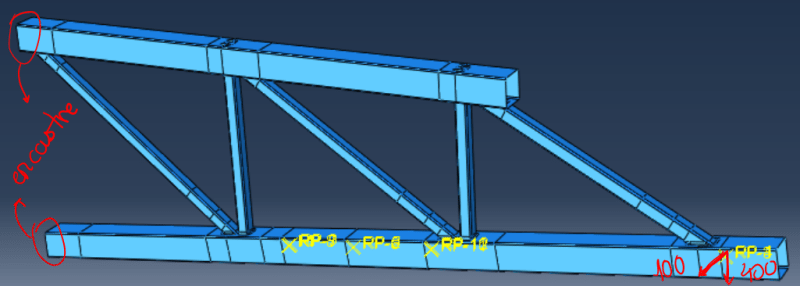
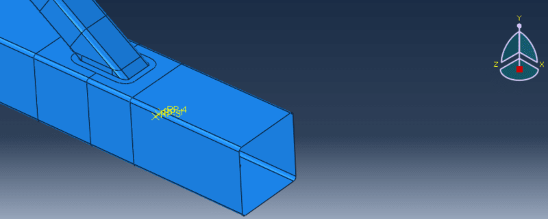
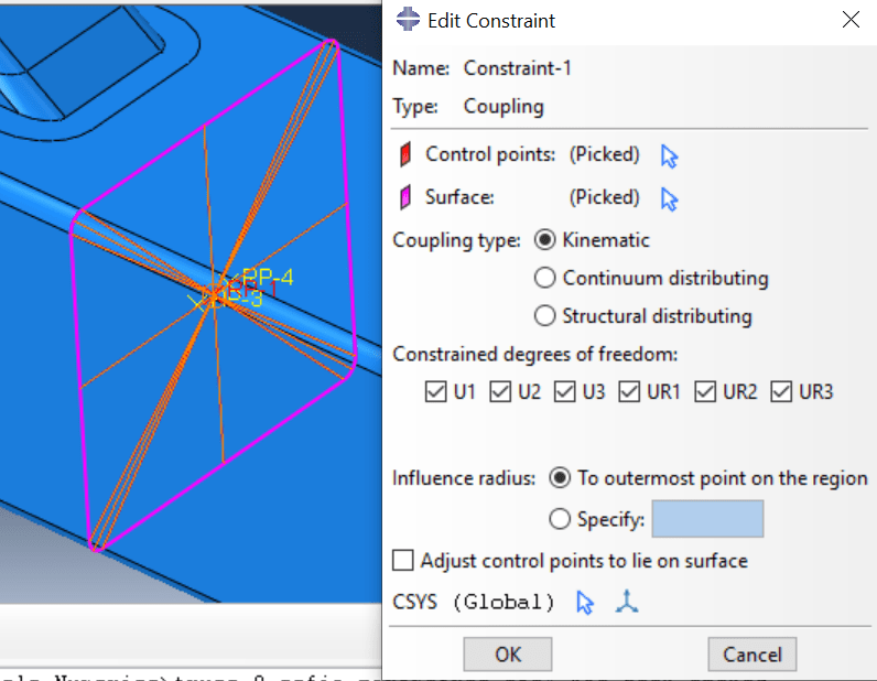
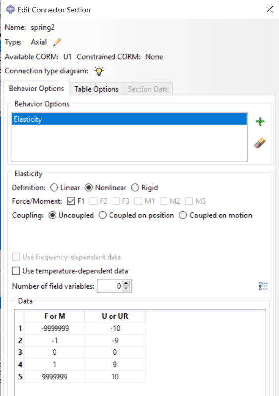
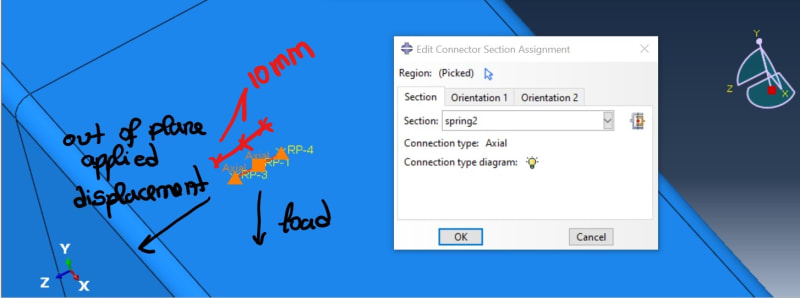
I'm analyzing a truss where I apply a vertical displacement (u2 direction and applied as 400mm) as well as an out of plane displacement (of 100 mm) in a reference point (RP1) that is connected to the chord section by a coupling constrain. At the same point, two springs were applied, one on each side, distancing 10 mm from the middle reference point. In the reference points at 10 mm from RP1, the out of plane displacement (u3 direction) was prevented as a boundary condition.
After running the model, I noted that the displacement in RP1 exceeded the 10 mm max displacement imposed by the boundary condition. Even though I know that the out of plane displacement is a value much bigger than the 10 mm distance, I was expecting the displacement to stop at 10 mm since the only reason I was using the out of plane applied displacement was to introduce imperfections in the model.
Can anyone help understand this behaviour? I will leave pictures for a better understatement.