Hello,
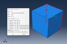
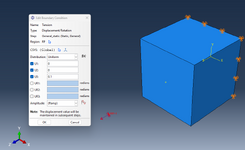
The answer to this is pretty simple. Let us assume you have a demo cube (solid element). Let us pin one side of the cube (U1 = U2 = U3 = 0) and let us apply a tensile loading on the other side (U1 = U2 = 0 and U3 = say 1) (See the attachments).
Let me create a Reference point and let me couple this RP to the side wherein the 1mm tensile displacement is going to be applied. So, the tensile displacement is not applied directly on the surface (but rather on the reference point). Request the Reaction Force as a history output for the RP region.
1. Apply a youngs modulus of 100e3 Pa for the material. Have a look at RF3 at the RP.
2. Change the youngs modulus to 100e9 Pa for the material. Have a look at RF3 for the RP.
The reaction force plot differs between the two cases. So, RF tells us how difficult or easy it is to implement the applied BC. This is one purpose of studying the reaction force.
Also, there is another application. Try requesting RF it on the region wherein you applied the pinned BC. Find RF3 for all the nodes involved in the 'Pin' BC definition region and sum up the reaction forces of these nodes. This is the reaction developed at the supports because of what is happening in the other parts of the body.
Now, note that the sum of the RF's at the pin region and the RF at the tensile BC region are equal in magnitude, but opposite in signs (+ and -). Add them and you will get 0 (netto).
So,
The study of RF has 2 purposes:
1. How difficult it is to implement the applied non-zero valued BC.
2. Reaction force developed at the location of the zero-valued BC (because of what is happening in the other parts of the body).
RF can only be seen at the region of BC application (but this can be a zero valued BC or a non zero valued BC).
Best Regards,
Vishakh Rajendran.