Tek-Tips is the largest IT community on the Internet today!

Members share and learn making Tek-Tips Forums the best source of peer-reviewed technical information on the Internet!

  • Congratulations JStephen on being selected by the Eng-Tips community for having the most helpful posts in the forums last week. Way to Go!

Out-of-Plane Blockwork Equation - 'd' clarification

Ants22

Structural
Joined
Jul 26, 2025
Messages
2
Hi All,
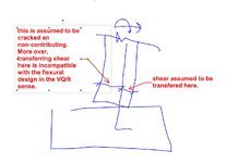
Just running through AS3700 for concrete blockwork Out-of-Plane Shear capacity, and just want to double check with the wider community: For 'd' (The effective depth of the reinforced masonry wall), say we have a wall which is 190mm thick and cover as 55mm and a bar size of N16 would the 'd' value be: (Option 1)190-55-(16/2)=127mm or would it be (Option 2)55+(16/2)=63mm?

I can see arguments for both but the example provided in 'CMAA reinforced cantilever walls' has Option 1 as there calculation. I would have though with the shear force acting on the starter bar would want to brake out of the starter out the back of a retaining wall, therefore would only engage the Option 2 depth of concrete?

AS3700 equation reference:
1753529335117.png

I would love any more examples of this, if anyone has any (Bonus point for AS3700 referenced material). Happy to be schooled in any way!

Thanks
Ants22
 
It sounds like you have a retaining wall with tension steel eccentrically placed towards the heel of the wall. In that case, option 1 is correct.

Think about your load path with how the load is applied to your section and how it will reach the support (footing). It may help to visualize by rotating the section 90 degrees in your mind and think about it like a cantilevered beam.
 
I do not have AS3700, but how does it define it in respect to out-of-plane shear? Would it not be whichever measurement takes you from the outside compression face to center of "tension" rebar center?
 
For 'd' (The effective depth of the reinforced masonry wall), say we have a wall which is 190mm thick and cover as 55mm and a bar size of N16 would the 'd' value be: (Option 1)190-55-(16/2)=127mm or would it be (Option 2)55+(16/2)=63mm?

You instincts are good here. What portion of the cross section you are relying on for shear depends on the direction of the shear.

Some codes, in some materials, will provide a lower limit on shear capacity where the shear depth gets a lot small than the overall depth. This is your 0.72h instead of dv in the North American concrete codes.

01.JPG
 
Thanks all for the replies.

Just for completeness and confirmation of my understanding, when considering the first portion of the equation f'vm.bw.d where
1753613377140.png
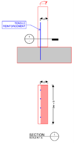
we are transferring the shear (within the concrete portion of the wall/equation) between the tensile reinforcement and extreme compressive fibre, as illustrated below:
1753613596210.png

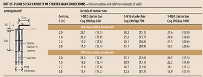
Ultimately, I'm trying to reproduce a table similar to be the below:
1753613877877.png
For the life of me, I can not reproduce the values they have provided. (Noting the document they have been obtained from is a 2012 but in double checking the variables, there doesnt seem to be any changes to them). Going to have to spend some more time in a spreadsheet to try figure out how they have come to the values obtained...

My only thought is that they have only considered the single core as a reinforced core and the remainder of the wall has been design as a unreinforced wall? Thoughts?
 
Is the equation that you are using intended for general shear or shear friction? Often shear friction is used for the starter condition.
 

Part and Inventory Search

Sponsor

Back
Top