I have a bit of a problem with the picture.
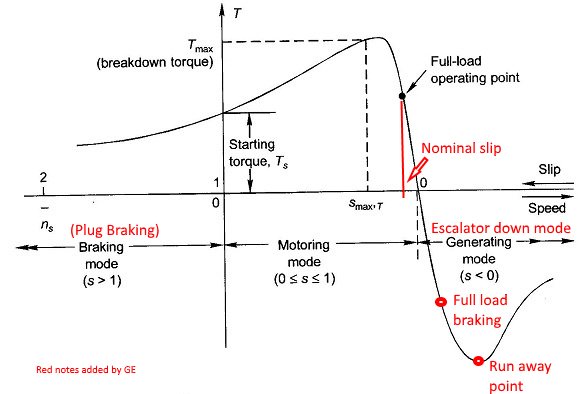
The curve is a typical curve for a DOL induction motor.
However the normal operation of a VFD is in the region between the full load operating point and the full load braking point.
To start a motor with a VFD frequency set so that the motor is at the point shown as the starting torque is wasteful and does not take advantage of the reduced starting current of the motor VFD combination.
To say this another way, that picture/curve and the operating points shown are valid for an induction motor started DOL.
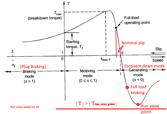
Normally the limits of VFD operation will be between the breakdown point and the runaway point or between the current limit points if set, for short periods of time.
Steady state operation or load RMS* operation will be between the full load operating point and the full load braking point.
*
Link See .pdf pages 49, 50, 51. RMS HORSEPOWER LOADING
Comments?
A question for Gunnar and Jeff:
It is my understanding that that curve may be used for VFD operation if the 0 point is the VFD output frequency and the slip is the motor normal slip.
eg: 1800 RPM - 1760 RPM = 40 RPM slip for a 1760 RPM motor
1500 RPM - 1460 RPM = 40 RPM slip for a 1460 RPM motor.
Is this correct or close to correct?
Bill
Bill
--------------------
"Why not the best?"
Jimmy Carter
")
