Tek-Tips is the largest IT community on the Internet today!

Members share and learn making Tek-Tips Forums the best source of peer-reviewed technical information on the Internet!

  • Congratulations MintJulep on being selected by the Eng-Tips community for having the most helpful posts in the forums last week. Way to Go!

Oddball Underpinning Condition 7

Status
Not open for further replies.

KootK

Structural
Joined
Oct 16, 2001
Messages
18,690
Location
CA
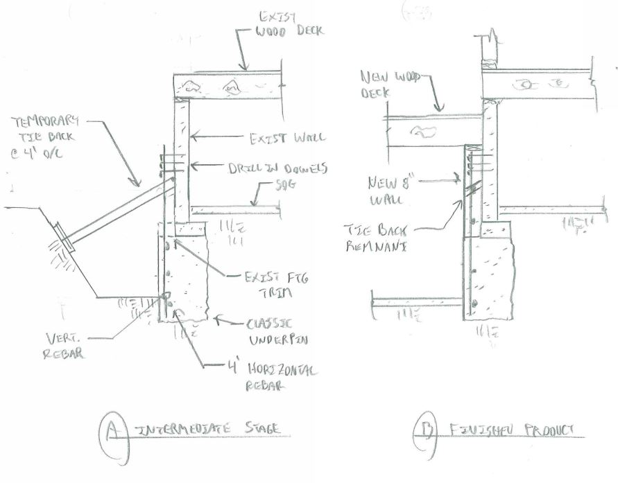
Attached, and shown below, is an atypical underpinning situation that I need to sort out for a one story light frame wood building. Some questions that I have include:

1) Can the system that I've shown be installed incrementally as regular underpinning would be?

2) Is there any way to hide the tie back anchors within the thickness of the wall somehow?

3) Is there some better way to do this? Maybe an L-shaped retaining wall installed as underpinning?

4) Should I do anything around the corners to address potential soil sloughing etc?

It's worth noting that the existing building will be demolished to the ground floor level before being rebuilt. Rebuilding the wall altogether is an option, albeit not preferred by the client.

20150113%20Underpining%20BMP.bmp


I like to debate structural engineering theory -- a lot. If I challenge you on something, know that I'm doing so because I respect your opinion enough to either change it or adopt it.
 
Critical question.......is the soil granular or clay? Do you have a soil report or experienced in this area to know the soil and water table conditions that you will encounter?.

If in clay, normally underpinning is done in 4 foot alternating segments.

If in sand, sheeting is often required.
 
Since underpinning is very expensive and difference in elevation is not alot, is it possible to move the step away from existing wall and avoid the expensive underpinning altogether?
 
No soils report yet. It's got a small time residential feel to it which usually means that soils reports are slow in coming or non-existent. The site can be expected to be silty/sandy concoction. Underpinning is pretty common in the surrounding area.

I like to debate structural engineering theory -- a lot. If I challenge you on something, know that I'm doing so because I respect your opinion enough to either change it or adopt it.
 
What abo9ut adding a new 8" thick concrete wall to the outside of the existing basement wall from floor to ceiling in the new basement space to counter the hinge?

Mike McCann, PE, SE (WA)


@MS: could do if the architect will let me. That would still need to be sequenced like traditional underpinning though, right? One issue is that I'd need to use an eccentric strip footing for the new wall and the top of that wall would be laterally supported by a wood diaphragm. I usually don't like to use eccentric footings with wood lateral support. Under gravity loads, I worry that the top of the wall will tilt over as the wood deck creeps. Maybe that's just paranoia. Please let me know if you think so.

I like to debate structural engineering theory -- a lot. If I challenge you on something, know that I'm doing so because I respect your opinion enough to either change it or adopt it.
 
I'm with Mike, Is the 8" that much floor space to lose?
 
and I think that's just paranoia. It appears to be a reasonably large diaphragm. That 3/4" pretty much acts like a rigid diaphragm. Block the first 2 joist spaces and stop worrying about it.
 
Your sketch shows the underpinning being completed in two pours per segment completed, i.e. excavate, pour footing, pour wall. This process will likely double the time to complete the underpinning. Could you look at increasing the wall thickness to match the footing width? This would potentially have a couple of advantages; 1) decrease construction time as footing and wall poured together and 2) the thicker wall could possibly be thick enough to act as a gravity retaining wall, thus reducing or eliminating the potential hinge. This will be one sided forming, which can be tricky. If the soil is stable enough not to sluff, the soil becomes the formwork on one side. The new, thicker fdn wall will intrude into the lower portion of the basement, but likely not more than 6 or 8 inches.
 
Thanks for the brutal honesty Jayrod. You know how it goes. 8" is no big deal but would cause the architect to have to redraw his plans an therefore hemorrhage fee.

I like to debate structural engineering theory -- a lot. If I challenge you on something, know that I'm doing so because I respect your opinion enough to either change it or adopt it.
 
KootK:

The only weight you are adding to the new strip footing that is not seen by the existing strip footing is the weight of the wall, and you can just make your new strip footing a little wider to pick it up. I would not be that worried about the load eccentricity in this case. As jayrod mentioned, block the top of the new wall to the existing diaphragm.

I would also add short horizontal tie rebar dowels from the new to the existing walls.

Contractors and Architects live me...

Mike McCann, PE, SE (WA)


Not live me, love me! Darn but I hate this machine!

Mike McCann, PE, SE (WA)


I don't see A as a realistic possibility. B works of course if the soil has sufficient standup time. I have seen soil nails walls done this way. If some care is taken such as drilling through a berm, then digging like hell, shooting on shotcrete with WWF and wet setting the anchor plates the building might not settle.
 
Since they have to bulldoze the new basement anyway, I would cut the existing SOG 5' from wall and dig it all out. Pour new footing and wall attached to the new upper SOG with rebars into the old SOG. But then I would not get this kind of job, as my way is not their way.

Garth Dreger PE - AZ Phoenix area
As EOR's we should take the responsibility to design our structures to support the components we allow in our design per that industry standards.
 
Yeah, fiddling with this feels like it's going to be way more complicated than just demolishing the wall and rebuilding.

With the hinge situation, you seem to have enough restraint to maintain stability if you actually design it as a hinge. If you can reasonably manage to dowel enough to transfer some shear across that point you can design this to work without making it continuous for moment or needing to install tie backs.
 
Sec. A-A is a simple, standard, concrete underpinning project. The only hitch is that the existing building is a "one story, light frame wood building." In most underpinning projects, if the height from the existing floor slab to the subgrade of the addition is less than ABOUT 10 feet and if the concrete underpinning pier is ABOUT 3 feet wide minimum, perpendicular to the face of the existing wall, then you can usually underpin without any bracing or tiebacks. Your excavation height is ABOUT 7 to 7.5 feet which is usually good. However, your building is light and probably will not provide sufficient normal force to the underpinning to prevent its overturning and/or sliding. The underpinning needs to be installed before trimming off the footing toe or trims just a section of the toe when each individual underpinning pit is excavated.

Figure out the depth of excavation required below the existing floor slab. Draw an underpinning pier about 3 feet wide, extending back behind the face of the basement wall, under the existing structure. Draw the earth pressure diagram and any lateral surcharge pressure diagrams behind the underpinning. Check overturning and sliding of the underpinning. If the safety factors are OK, you are good. If not, you will need to make the underpinning thicker than 3 feet, or allow the front face of the underpinning to project farther into the proposed basement, or you will need to install some type of permanent lateral support for the underpinning. This usually is expensive and causes the home owner to move the new basement away in order to eliminate the need for underpinning.

Sec. B-B just shows the return of the new basement wall at each end of the underpinned section. Again, this is no big deal EXCEPT that you may have a vertical excavation depth of ABOUT 10 or 11 feet (= 7 to 7.5 feet plus the depth of about 3 to 3.5 feet from OG outside the building) at each end of the Sec. A-A underpinning. You would then need to install a perpendicular underpinning return at each end of the Sec. A-A underpinning or install some temporary sheeting until you are far enough away from the existing building to allow a safely sloped open excavation that does not undermine the existing building.

 
Thanks for all of the excellent suggestions. I've worked up a proposed scheme for collective review (attached and shown below). The questions that I have include:

1) Is this possible?

2) Is there any way to get rid of the temporary tie-back "remnant".

3) Could the underpinning and the new 8" wall be poured in one shot somehow, eliminating the temporary bracing?

4) The underpinning will be done in 4' segments which means that the horizontal steel in the underpinning will be discontinued every four feet. The new wall poured above would be poured in one shot potentially. I feel as though this might be an issue for shrinkage cracking. Perhaps the way to go is to just warn the architect and suggest furring and drywall on the wall face.

20150114%20Underpinning%20Alternative%20JPEG.JPG


I like to debate structural engineering theory -- a lot. If I challenge you on something, know that I'm doing so because I respect your opinion enough to either change it or adopt it.
 
#2 - Yes, just box out around the raker and remove later and fill in. This is typical. Unless you meant something different. That raker can be timber.

#3 - Usually you would want to drypack and shim the top of your underpinning usually which may preclude a one pour deal. Although since you are demo'ing most of the building you may not need much pre-loading so might be possible to count on the head to to fill in all voids and full bearing.
 
#1. Looks very possible.
#2. Depends on the loading obviously, but if you excavate out in 4ft segments you might be able to get rid of the raker by making the new footing large enough to work as a gravity wall. I will often assume some cohesion (real or apparent) in the soil at least for the temporary condition. It exists or you wouldn't be able to make the cut to begin with. If the soil behind it can't dry out I regularly count on it for temporary conditions. 50 psf cohesion goes a long long way.
#3. You would have to cut off the existing footing on the way down, but I do not see why not.
#4. I always have the contractor drive rebar into the soil each side. You are not going to get a full Codified lap splice, but you get continuity.
 
Status
Not open for further replies.

Part and Inventory Search

Sponsor

Back
Top