The N
req values are simply tabulated values in that table - they are driving the calculations for the allowable loads given in the rest of the table. That is, you determine the actual bearing length that you need (based on beam properties and loading). Then, you take that value and enter the design table to find the allowable capacity of a seated angle based on the bearing length required. The longer the required bearing length, the larger the eccentricity is on the projected angle leg, reducing the overall capacity of the connection.
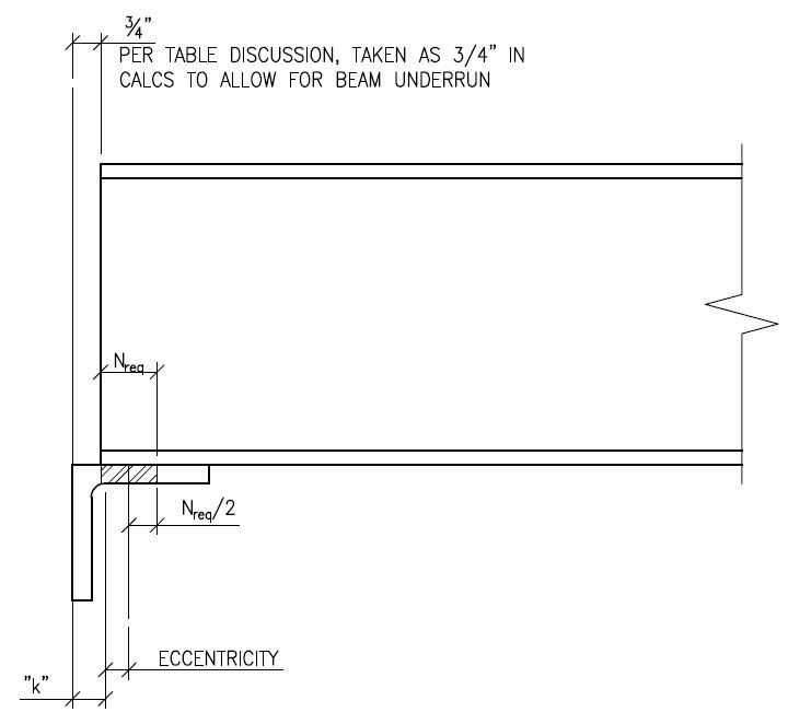
If you are trying to determine the relationship of the N
req to the outstanding leg strength reported in the table, it is as follows:
The seat angle is checked for shear and for bending of the horizontal angle leg to find the allowable load on it. As noted in the table, values above the solid black line are controlled by shear, values below are controlled by bending. Bending in the leg is found by multiplying the eccentricity of the bearing point times the shear load. Or, conversely, the allowable load can be found by dividing the max allowable bending moment on the angle leg by the eccentricity of the connection. The eccentricity is the clear space between the beam end and the back of the angle plus 1/2 the bearing length (N
req) minus "k" of the angle (which is generally the angle leg thickness plus 3/8") See image below:
So, if we have a 3/8 by 6" long angle, we can calculate the allowable moment in the leg per spec section F11, Mn=Mp=FyZ. so 36ksi * 6in * 0.375^2 / 4 = 7.59 in-kip and phi*Mn = 0.9 * 7.59 = 6.831 in-kips
Then, lets say our required bearing area is 1", this would give an eccentricity of 3/4" + 1/2*1" - 3/4" = 0.5"
Finally, our allowable shear load would be phiMn/eccentricity = 6.831 in-kips / 0.5in = 13.66 kips. This corresponds to the 13.7 kip value shown in the table.