Tek-Tips is the largest IT community on the Internet today!

Members share and learn making Tek-Tips Forums the best source of peer-reviewed technical information on the Internet!

  • Congratulations cowski on being selected by the Eng-Tips community for having the most helpful posts in the forums last week. Way to Go!

Non linear and buckling analysis 5

Status
Not open for further replies.

Saedhalteh

Civil/Environmental
Joined
Nov 8, 2019
Messages
43
Location
JO
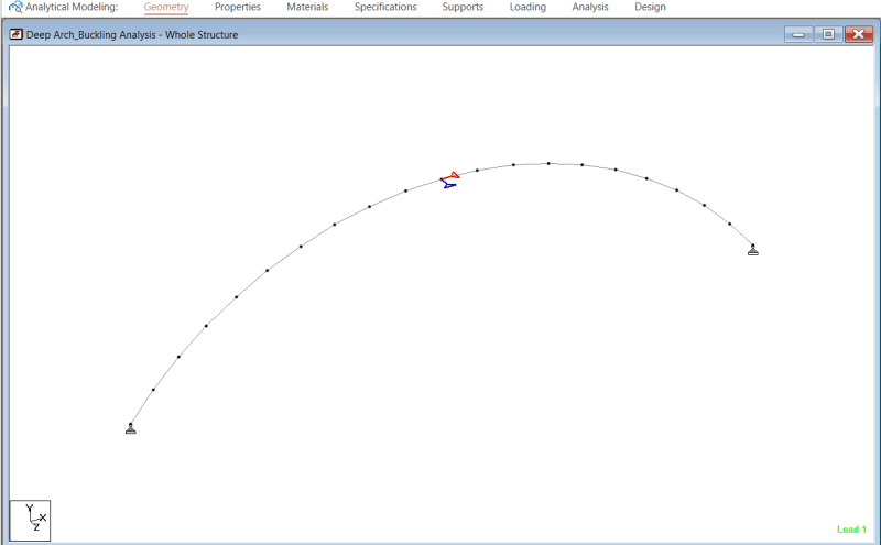
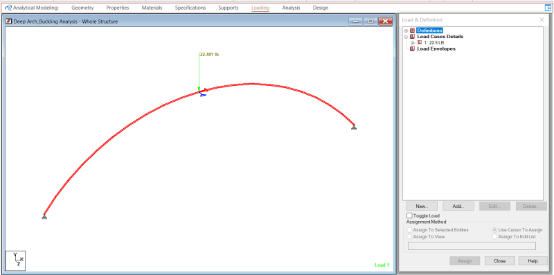
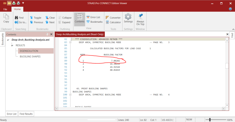
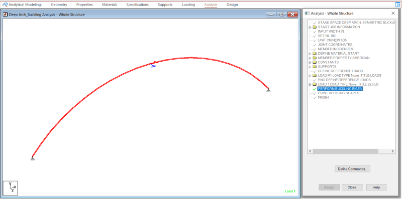
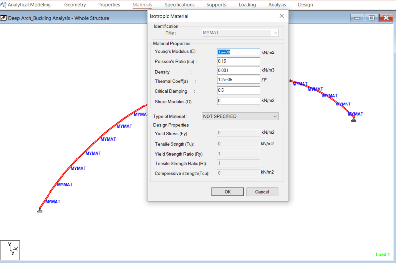
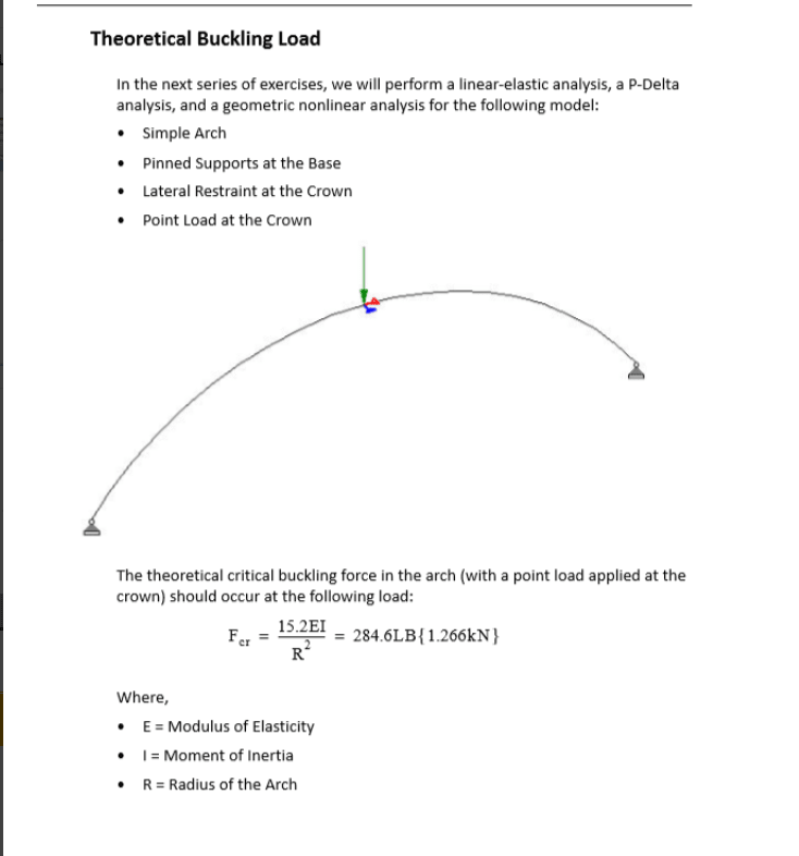
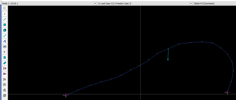
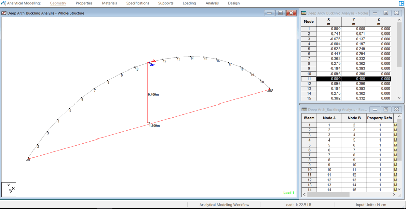
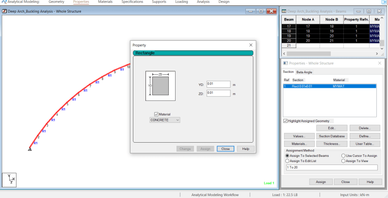
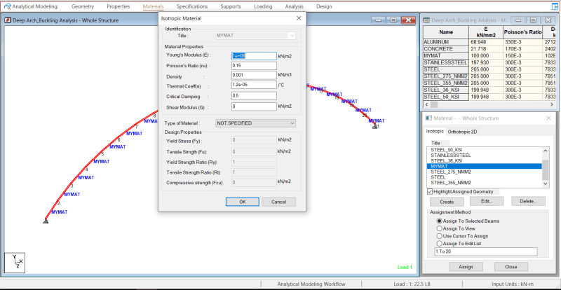
There is a ptoblem that I tried to solve with different types of analyisis Using STAAD software ,for the arched beam that I am trying to analyze the theoretical buckling load was 284 lb , using the linear elastic analysis it didnt show any failure . P delta analysis indicated failure at load much higher than 284 , non linear analysis gave the most accurate result with buckling load around 280 , but using the buckling analysis it showd me that the buckle should occur at 157.5 , I searched and understand the diffrences between the linear, p-delta and non linear analysis. My question is why the buckling analysis gave results that differs alot from the non linear analysis ? Can someone help me with that.
 
well buckling analysis is a approximation only
It is a good approximation if the pre buckling range is rather linear...and is a not so good approximation if pre buckling range is geometric nonlinear
it also depends on the used program...and the used element type...
the best is to solve some problems (systems) where the solution is knows from literature
 
Can you share a picture of your model (showing its geometry, load and bounday conditions) ? Simple 2D scheme will be enough. Also could you provide a reference for your analytical solution (basically where you’ve found formulas for buckling of your structure) ? This would help me find the reason of such discrepancy in results.

In case of arches typical buckling mode is snap-through. Linear stress analysis won’t give you results for this case but linear buckling analysis usually gives highly inaccurate results as well. In most cases it overpredicts the buckling load (actual structure will buckle at lower load than indicated by eigenvalue buckling analysis). However in snap-through problem it may significantly underpredict the buckling load. To obtain correct solution for such problem you have to use nonlinear analysis.
 
I'm not a fan of using software to figure any kind of raw buckling load. (As opposed to a code allowable.) There is just too much it doesn't take into account. (Initial imperfections being one of them.)

For a arch buckling load, 'Guide to Stability Design Criteria for Metal Structures' should be a adequate reference. It has buckling loads for both in-plane (snap through) and out of plane loads. I've used it many times myself.
 
See:
Buckling of rings and arches

… especially the last paragraph.

I'd recommend an analysis with geometric non-linearity, material non-linearity if it is reinforced concrete (or use a conservative estimate of the cracked stiffness), initial imperfections, short members, asymmetric loading, and appropriate direction of loading on deformed elements.

Check against the values given by buckling theory, and if the buckling load from the analysis under asymmetrical loading is not substantially lower, examine the model to see where you went wrong.

Doug Jenkins
Interactive Design Services
 
xxx_qxdudp.png
xxxxx_i8r7ja.png
xxxxxxxxxxxxxxx_vdlwgq.png
xxxxxxx_yh9nir.png
xxxx_fxp1d0.png
Capture_s8xvu3.png


Thank you all for the answers, really appreciated. Here are some images for the arched beam that I am trying to analyze, the theoretical buckling load is as shown, equal to 284. But the staad buckling load factor was 7 for the first mode, which means that the buckle will happen at 7*22.5=157.5 lb which is much lesser than 284 lb. and this is where I lost it and can not really understand why it differs alot from the result from the nonlinear analysis .
 
Does setting the shear modulus to a non zero value get better agreement?
 
Where did the 15.2 factor come from?

I couldn't find anything for buckling of an arch under point loads in Roark, Timoshenko & Gere, or Pilkey. I didn't find a definitive simple formula on-line either, but the paper below gives experimental and FEA results for an aluminium arch under central point loads, and also discusses discrepancies with earlier work. Note that the buckling mode in this case is out of plane buckling, resulting in combined bending about the weak axis and torsion.
Buckling of monosymmetric arches under point loads

I did some 2D analyses using Strand7 and found good agreement between a linear buckling analysis and an incremental analysis with full geometric non-linearity and elastic material properties, provided a small initial imperfection was included in the non-linear model . Results are shown in the graph below:
arch_buckling_iplc5h.png


The results labelled concrete are from my analysis with a 10 m span and 1 m wide x 0.3 m deep reinforced concrete section, with pinned or fixed end conditions. The aluminium results are from the paper linked above, which was a 500 mm span with pinned ends allowing in plane and out of plane rotation and warping at the supports.

To allow a better comparison of results could you supply:
The arch span and height and base angle.
Cross section details and material.
End conditions.

It would also be useful to check the deformed shape plot from the buckling analysis (my strand7 results shown below):
arch_buckling2_obk5fe.png


Doug Jenkins
Interactive Design Services
 
Saedhalteh, could you give more info about the problem (i.e. geometry, cross-section, and material)? I have found a (elastic) buckling formula in the reference I mentioned for a point load at the apex (applicable under certain geometries). And I will run it if you give me that info.
 
ASCE Journal of Structural Engineering said:
It is found that the design equation for steel columns cannot be used directly for steel arches in uniform compression, nor can the design interaction equations for steel beam-columns be used directly for steel arches under nonuniform compression and bending.

Link to abstract of the technical paper "In-Plane Buckling and Design of Steel Arches", Published Nov. 1999


Hope this helps.
 
WARose, Really appreciate your concerns and help .
If you want I can send you the staad file for the non-linear and buckling analysis.

geometry_f4xtvv.png
section_xmmadt.png
material_stlfmy.png
 
Saedhaltech - could you let us know where the formula Fcr = 15.2EI/R^2 came from?

Also I'm assuming the supports are pinned. Is that right?


Doug Jenkins
Interactive Design Services
 
Here is another point of reference. Using the 1D Elements program ( the calculated buckling load is 187 pounds (Eigenvalue solution).

arch_image_hodeeh.jpg


This is the input file I used (I converted the values to English units)

NOTE: I am not sure if you meant to restrain the crown point in the X-direction or not. I assumed not, but I am not familiar with STAAD and can not identify what the icons at the top mean. If you restrain in the X-direction at the top, the value is 380 lb.

Brian
 
[red]EDIT[/red]: Below is changed because I misunderstood what you are using. Please confirm you are using structural steel. I can't read your input. The modulus of elasticity appears to be 1E+08 kN/m^2.
-------------------------------

Ok, looking in the reference I mentioned, for circular arches (which this appears to be, please confirm that), I used the following equation:

Pe=Α((EI/(S)2)

Where:
Pe=equals the critical elastic axial stress (at quarter points of the span) [ult. value]
A= Constant (I used 7.6, see Table 16.5 in the 3rd edition of the reference I mentioned)
E=Modulus of Elasticity (I used 14,503 ksi in my calculations, based on your input above)
I= Moment of Inertia for cross section
S=1/2 of the arch span, i.e. the circumference distance from the support to the apex/crown

With all that, and using a safety factor of 3 (since the load outcome is in ult.), I get a allowable stress of 29.8 psi (205 kN/m^2).

In other words: virtually nothing. I think you will get the same sort of allowables when you consider the out-of-plane buckling as well. (Which you should check for your developed moments if it isn't braced out-of-plane.)

Comment: this thing is mighty slender. Are you sure it's a 0.01 meter x 0.01 meter cross section? That's essentially nothing. What is this intended to do? (Sorry if you have already said and I missed it.)
 
Checking my graph of buckling factors, I noticed I had actually used the horizontal half-span in the calculation, rather than the radius. Since the values from the paper used the radius I have updated the results so they are comparable. I have also removed the line for supports with moment restraint, since the analysis in the OP is pinned at the base:
arch_buckling-rev1_xo4a6h.png


Note that my results (blue line) are for a 2D analysis and the paper results (green line) are for a 3D analysis including out of plane buckling, with no torsional or warping restraint at the base, and no restraint at the crown.

My results for the structure as posted by Saedhaltech are:
arch_buckling-res_q57l94.png


The base supports are pinned for moments about the Z axis in all cases, and fixed for moments about X but pinned for Y and Z for the 3D analyses.

The loads are all point loads at the crown that will cause buckling, with no safety factor.

Unlike column buckling, the applied loads cause large deflections before buckling, such that the geometry at the buckling load is significantly different to the unloaded structure. This accounts for the difference between the linear buckling results and the non-linear analysis.

Also note that all analyses assumed linear elastic material behaviour. Except for the 3D analyses with no lateral crown support, the material would become non-linear well below the calculated buckling load.


Doug Jenkins
Interactive Design Services
 
As others have said, eigenvalue buckling analysis is unconservative, and in my experience by about 10-15%. Non-linear geometry analysis should be accurate. Initial out of straight usually doesn't make much difference, though you do need an initial perturbing displacement or force. P-delta is a weird formulation designed to be similar to certain code analysis, and I would not waste a lot of time on it.
 
Status
Not open for further replies.

Part and Inventory Search

Sponsor

Back
Top