I've only recently started studying EMI and common-mode filtering and need some design advice, so please bear with me.
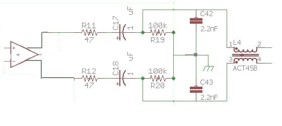
I have an audio circuit project that I am working on, to which I want to add common-mode filtering at the output terminals to prevent any RF (especially in FM range) picked up by the cables from being demodulated into the audio. A schematic of the output circuit including a common-mode filter consisting of a CM-choke and 2 caps to chassis is attached. I'm assuming the source to be a common-mode voltage source located along the cable somewhere, with the source impedance being the cable itself. I am attempting to minimize the RF voltage at the load by shunting the CM current to the chassis (chassis is earth grounded, and signal gnd is connected to chassis in one place).
In order to simulate the frequency response accurately, I need to include source and load cm impedances in the simulation. I have calculated the cm load impedance as approx 24 Ohms, looking into the circuit from the filter caps, and have measured it on the actual device up through 5MHz, and results were pretty much dead on. However, I don't exactly know how to measure the source impedance (I assume this is simply the cable impedance applying a common-mode signal to both conductors, likely twisted-pair). I've simulated the results with a wide range of different source impedances to get an idea of where the response is going to lie (graph attached in next post), but now I'd like to confirm it via measurement.
I have a 30MHz signal generator and 100MHz scope, but nothing fancy (expensive) like a spectrum analyzer. So now my questions: 1) Is the way I'm visualizing the RF noise circuit correct (voltage mid-cable, common-mode on both conductors)? 2) Is the way I'm thinking about this design process correct (minimizing RF voltage at the "load impedance", or the other side of the filter)? and finally 3) If this is correct, what is the best way to measure twisted pair cable impedance with the equipment I have? I was thinking of just using a shunt resistor and something like 100-1000ft of cable to get enough resistance to make an accurate measurement. I'd be happy with a value up through 10MHz for now, just to give me an idea of how close my simulation matches reality.
Thanks for any input.