Hello All,
Long time lurker here!
I have a question regarding how one would inspect the image below.
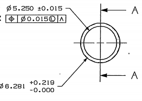
It is a pipe that has a machined OD and ID.
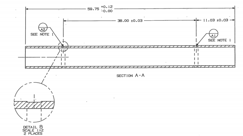
The pipe has two target datums "rings" on the OD, A1 and A2, which when centered to one another their axis becomes Datum A.
The pipe's ID is machined to the Pipe's OD.
How Pipe is set up on the lathe:
[ol 1]
[li]Using a 4 jaw chuck, chuck to the A2 datum target end of the pipe[/li]
[li]Use a steady rest to support the non-chucked datum target A1 end on the steady rest band OD[/li]
[li]Indicate around the steady rest band OD to find the center point of datum band target A2[/li]
[li]Using the 4 jaw chuck, adjust chucks so that the chucks are centered to the A2 datum target band center point[/li]
[li]Indicate around the steady rest band OD to find the center point of datum band target A1[/li]
[li]Using the steady rest, adjust its supports so that the supports are centered to the A1 datum target band center point[/li]
[li]The shell barrel should now be set up center and level so that as the lathe head stock rotates, the pipe rotates around the Datum A axis[/li]
[/ol]
How to inspect the pipe's ID position to the OD datum target "rings" that create Datum A axis:
[ol 1]
[li]Determine a “common” zero location around the circumference of the part
[li]Insert indicator on the Datum A axis.
[li]Set zero on the ID at the determined "common zero location” and record indicator value. This value should read 0.000"[/li]
[li]Rotate the pipe 90 degrees to the 90 degree location and record indicator value 0.XXX" (lets say the indicator reads 0.007")[/li]
[li]Rotate the pipe 90 degrees to the 180 degree location and record indicator value 0.XXX" (lets say the indicator reads 0.012")[/li]
[li]Rotate the pipe 90 degrees to the 270 degree location and record indicator value 0.XXX" (lets say the indicator reads 0.003")[/li]
[li]Rotate the pipe 90 degrees back to the "common zero location” and the indicator should read 0.000"[/li]
[/ol]
The indicator readings above would result in a total indicator reading (TIR) of 0.012" and an actual position of 0.0127" from true position.
Actual position from true position is calculated using the following equation:
Is the above a correct way in which you could measure the actual pipe's ID position?
Thank you for your time in advance!
Long time lurker here!
I have a question regarding how one would inspect the image below.
It is a pipe that has a machined OD and ID.
The pipe has two target datums "rings" on the OD, A1 and A2, which when centered to one another their axis becomes Datum A.
The pipe's ID is machined to the Pipe's OD.
How Pipe is set up on the lathe:
[ol 1]
[li]Using a 4 jaw chuck, chuck to the A2 datum target end of the pipe[/li]
[li]Use a steady rest to support the non-chucked datum target A1 end on the steady rest band OD[/li]
[li]Indicate around the steady rest band OD to find the center point of datum band target A2[/li]
[li]Using the 4 jaw chuck, adjust chucks so that the chucks are centered to the A2 datum target band center point[/li]
[li]Indicate around the steady rest band OD to find the center point of datum band target A1[/li]
[li]Using the steady rest, adjust its supports so that the supports are centered to the A1 datum target band center point[/li]
[li]The shell barrel should now be set up center and level so that as the lathe head stock rotates, the pipe rotates around the Datum A axis[/li]
[/ol]
How to inspect the pipe's ID position to the OD datum target "rings" that create Datum A axis:
[ol 1]
[li]Determine a “common” zero location around the circumference of the part
This can be done on a manual lathe be placing a temporary mark on the OD (in example a piece of tape)
This can be done on a CNC lathe by indexing to zero degrees
[/li][li]Insert indicator on the Datum A axis.
This can be a dial indicator that has to be read when inside the pipe using a flashlight.(difficult)
Or it can be an electronic indicator that is wired to a digital readout located outside of the pipe ID.(easier if you have the electronic indicator)
[/li][li]Set zero on the ID at the determined "common zero location” and record indicator value. This value should read 0.000"[/li]
[li]Rotate the pipe 90 degrees to the 90 degree location and record indicator value 0.XXX" (lets say the indicator reads 0.007")[/li]
[li]Rotate the pipe 90 degrees to the 180 degree location and record indicator value 0.XXX" (lets say the indicator reads 0.012")[/li]
[li]Rotate the pipe 90 degrees to the 270 degree location and record indicator value 0.XXX" (lets say the indicator reads 0.003")[/li]
[li]Rotate the pipe 90 degrees back to the "common zero location” and the indicator should read 0.000"[/li]
[/ol]
The indicator readings above would result in a total indicator reading (TIR) of 0.012" and an actual position of 0.0127" from true position.
Actual position from true position is calculated using the following equation:
2 X SQRT ((x2)+(y2))
2 X SQRT ((0.0022)+(0.0062))
= 0.0127"
Is the above a correct way in which you could measure the actual pipe's ID position?
If yes and the above is performed at multiple elevations through the ID of the pipe, could the worst case actual position be considered the actual position of the pipe ID overall?
If not, what would be a proper method of inspection? (without using a CMM or laser tracker)
Thank you for your time in advance!