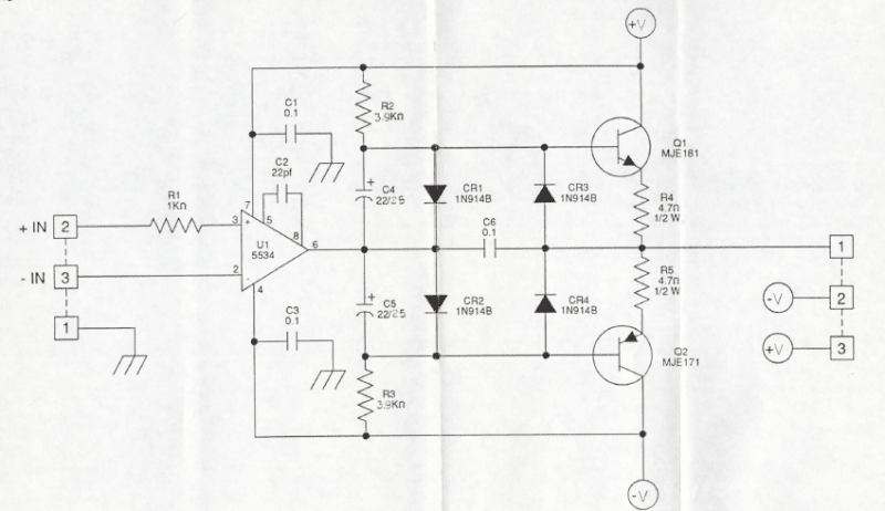
This is a classic AB amplifier design.
Some insights:
CR1, CR2, CR3, CR4 exist to keep the bias of the base of Q1 and Q2 two diode drops apart, or to be more specific, two Vbe junction drops apart. The reason for two sets of diodes is to maintain that bias voltage when the input voltage transitions are positive or negative.
If this is set up as a module, a feedback resistor network needs to be added from the output (pin 1, on the right) to the negative input of the op-amp (pin 3 on the left)Two resistor feedback net will establish overall gain, and will help improve the linearity of the output stage.
The output can source current into the load (Q1 on and pumping out current) or sink current out of the load (Q2 on)
Crossover behavior (As Q1 shuts down and Q2 turns on, or vice versa) can be a little glitchy, and the feedback amplifier feedback that include the AB amplifier in the loop helps with that, within the bandwidth limitations of the op-amp.
These were commonly used in audio amplifier designs back in the 1960-1980 era, before Class D switching amplifiers started to dominate audio amplifier design.
Jerry Twomey, Author of:
"Applied Embedded Electronics
Design Essentials for Robust Systems"