Hey everyone,
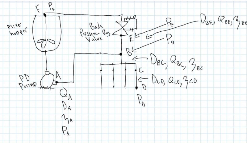
I have been working with this fluid system where we are pumping a thixotropic slurry with a positive displacement pump at a known flow rate (Qa) through a section of tubing up to a tee (B). The flow rates I see us working in yield a Re < 2300 so I am assuming we are laminar. At the tee we split to a discharge line (B-D) where we are pushing the slurry up against discharge which can accept a maximum flow rate if the necessary pressure is available to push the slurry through the volumetric flow control at D - I don't think we can say that D is at ambient pressure as slurry is pushed into a known volume, displacing the air through a loose seal, though maybe it is technically at ambient. The other branch of the tee goes up to a backpressure regulating valve where we add a set amount of backpressure to the lines to ensure our pressure at D is sufficient for the discharge we require - from testing I know what I need Pd to be, and from the pressure drop in the line I can figure out what additional backpressure we need to add in order to achieve this. After the backpressure regulating valve at E we return up to the hopper in a recirculation line E-F. So one side of the tee (B) dumps into the discharge (D) into a blocked
I have used the Power Law and am able to calculate the viscosity of the slurry at each diametrical/flow rate change in the system to help me then calculate the head pressure required to move that slurry through various sections of line at a set flow rate.
The question I'm running into is that we know the flow rate at A as we have a PD pump...I would like to just assume that we will be seeing our maximum/desired flow rate at D and that the rest of the flow will go up through the return line, however my calcs show that we will have a higher pressure drop from B-D than B-F due to the diameter change which we incur at C (shrink down significantly). Needless to say I can't say that we'll be seeing the maximum flow rate at D with the flow rate we are pushing at A. Again, I can calculate the viscosity at each point in the system, but I require the flow rate to do so as it is shear thinning. My current calc has me setting Qcd at my desired flow rate (the maximum which can be let through there), pushing the rest of Qa up through Qbe, and applying enough backpressure at the regulator to get Pd after the pressure drops from just the flow from Qcd...I just don't think I can assume these flow rates will be correct at the tee.
I haven't found a good method to determine how the flow rate will split at B in this scenario. I don't see a way to use Bernoulli's here, nor does poiseuille's law seem to have a place here.
I have seen mentions of "trial and error" (which sounds like a rough approach) where I can plot the flow rate vs pressure drop from B-F and do the same for B-D and find out at what flow rate they have the same pressure drop. If I do this approach then I suppose I would just add those flow rates and set that to be the flow rate from the pump, Qa? I'm just not seeing how that ties into me achieving the pressure Pd that I require, and how the backpressure regulating valve comes into the equation there.
Any thoughts on how I could proceed in determining what I need to set Qa to to achieve a desired Qcd and Pd in this scenario?