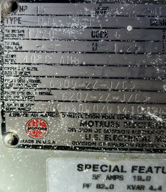
Design B;
Cowern Papers said:
Motor design letters
The National Electrical Manufacturer’s Association (NEMA)
has defined four standard motor designs using the letters
A, B, C and D. These letters refer to the shape of the motors’
torque and inrush current vs. speed curves. Design B is the
most popular motor. It has a relatively high starting torque
with reasonable starting currents. The other designs are only
used on fairly specialized applications. Design A is frequently
used on injection molding machines that require high pullout
torques. Design C is a high starting torque motor that is
usually confined to hard to start loads, such as conveyors that
are going to operate under difficult conditions.
Design D is a so-called high slip motor and is normally limited
to applications such as cranes, hoists, and low speed punch
presses where high starting torque with low starting current
is desirable. Design B motors do very well on most HVAC
You need 18 Amps and an extra 120 Volts. That's 2.16 KVA.
Add 25% per code and we have 2.7 KVA.
A pair of 480:120V, 3 KVA or larger lighting transformers should do the job.
We used to mount the transformers adjacent to the motors and trim the overload settings in the ratio of 5/6 or 6/5 as needed.
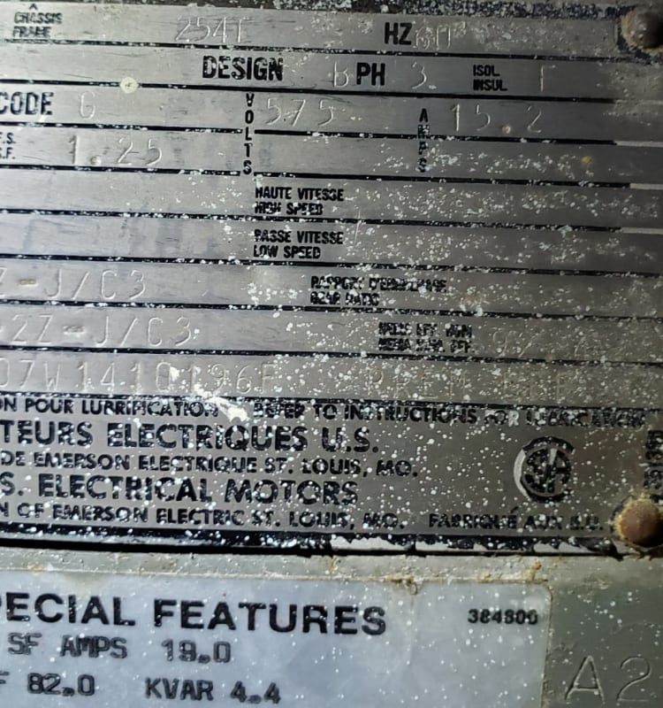
Cowern Papers said:
In addition to the standard numbering system for frames,
there are some variations that will appear. These are itemized
below along with an explanation of what the various letters
represent.
C Designates a “C” face (flange) mounted motor. This
is the most popular type of face mounted motor and
has a specific bolt pattern on the shaft end to allow
mounting. The critical items on “C” face motors are
the “bolt circle” (AJ dimension), register (also called
rabbet) diameter (AK dimension) and the shaft size
(U dimension). C flange motors always have threaded
mounting holes in the face of the motor.
D The “D” flange has a special type of mounting flange
installed on the shaft end. In the case of the “D” flange,
the flange diameter is larger than the body of the
motor and it has clearance holes suitable for mounting
bolts to pass through from the back of the motor into
threaded holes in the mating part. “D” flange motors
are not as popular as “C” flange motors.
H Used on some 56 frame motors, “H” indicates that the
base is suitable for mounting in either 56, 143T, or 145T
mounting dimensions.
J This designation is used with 56 frame motors and
indicates that the motor is made for “jet pump” service
with a threaded stainless steel shaft and standard 56C
face.
JM The letters “JM” designate a special pump shaft
originally designed for a “mechanical seal”. This motor
also has a C face.
JP Similar to the JM style of motor having a special shaft,
the JP motor was originally designed for a “packing”
type of seal. The motor also has a C face.
S The use of the letter “S” in a motor frame designates
that the motor has a “short shaft”. Short shaft motors
have shaft dimensions that are smaller than the shafts
associated with the normal frame size. Short shaft
motors are designed to be directly coupled to a load
through a flexible coupling. They are not supposed to
be used on applications where belts are used to drive
the load.
T A “T” at the end of the frame size indicates that the
motor is of the 1964 and later “T” frame vintage.
U A “U” at the end of the frame size indicates that the
motor falls into the “U” frame size assignment (1952 to
1964) era.
Y When a “Y” appears as a part of the frame size it means
that the motor has a special mounting configuration.
It is impossible to tell exactly what the special
configuration is but it does denote that there is a
special non-standard mounting.
Z Indicates the existence of a special shaft which could
be longer, larger, or have special features such as
threads, holes, etc. “Z” indicates only that the shaft is
special in some undefined way
I have mentioned before, a customer we used to service.
The business was cutting and bending re-bar.
The original plant was based on 480 Volts.
The company was associated with a plant in Ontario where 575 Volts had been the standard voltage for decades.
The plant was moved to a new location and BC had gone from 480 Volts to 600 Volts as the standard voltage.
The new plant featured an integrated service with a 600 Volt MCC and underground conduits to the locations of 600 Volt machines.
The next section was an auto-transformer stepping 600 Volts down to 480 Volts.
Finally there was a 480 Volt MCC with underground conduits to the 480 volt machines.
There was no easy way to run from the 600 Volt section to the 480 Volt section.
Then they brought a 575V (600V) machine in from the eastern plant to replace a 460V (480V) machine.
A pair of small transformers connected in open delta solved that.
Then a 575V motor failed and was replaced with a 460V motor from spares.
A pair of small transformers connected in open delta solved that.
After a few years, we had open delta auto-transformers all over the plant.
--------------------
Ohm's law
Not just a good idea;
It's the LAW!