greznik91
Structural
- Feb 14, 2017
- 186
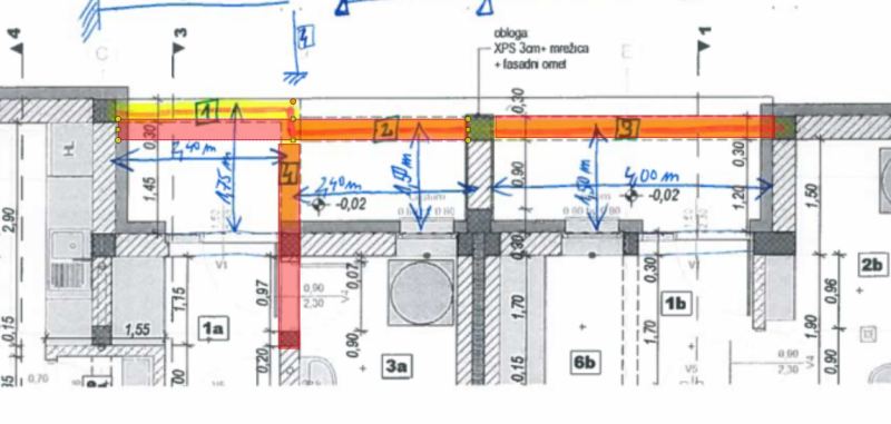
I have to design RC beams that are partly integrated into RC slab. I dont know how to model/calculate this since I dont trust FEM softwares for this kind of things since I almost made a huge mistake with something similar once upon a time.
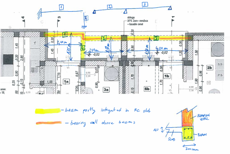
RC beams are marked yellow and red line is a bearing masonry wall above beams. Design load on beams are approx. 50 kN/m.
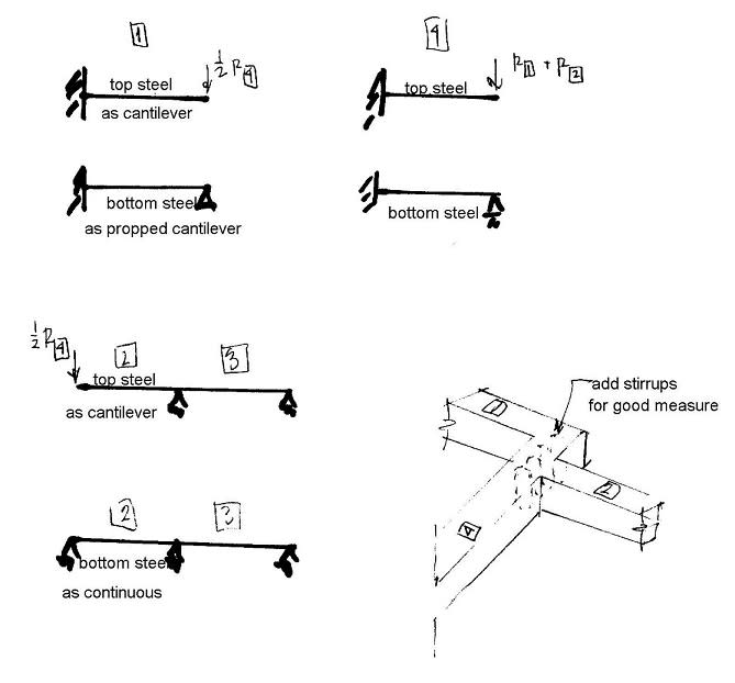
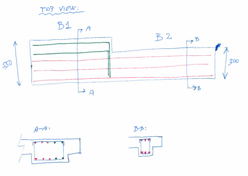
Id model beam 1 and beam 4 as cantilever beams but Im wondering how much does beam 4 actually helps since load is transfered in direction of stiffnes (bearing wall above beams - red line)? Is it problematic that beam 1 and beam 2 are not in the same line? If I move beam 1 in the same line as beam 2 I cant design it as cantilever since it would be a simple supported beam. How would you model this?
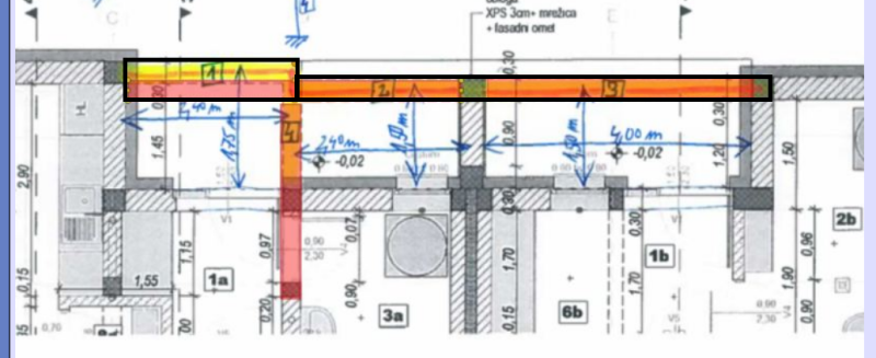
RC beams are marked yellow and red line is a bearing masonry wall above beams. Design load on beams are approx. 50 kN/m.
Id model beam 1 and beam 4 as cantilever beams but Im wondering how much does beam 4 actually helps since load is transfered in direction of stiffnes (bearing wall above beams - red line)? Is it problematic that beam 1 and beam 2 are not in the same line? If I move beam 1 in the same line as beam 2 I cant design it as cantilever since it would be a simple supported beam. How would you model this?
![[smile]](/data/assets/smilies/smile.gif "[smile] [smile]")