AnthonyJ777
Mechanical
Hello all,
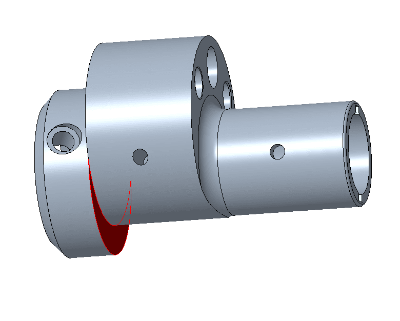
I'm working on a model in Creo 6.0 of an eccentric shaft for a rotary (Wankel) engine. I'm struggling to model this draft feature on one of the lobes. You can see from the drawing it starts out as a 45 degree draft and then tapers to a 30 deg draft but I've yet figure out how to blend a draft like that into the outside diameter of the lobe.

Here is where I'm at with the model
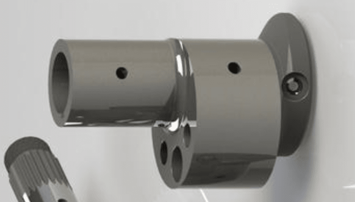
Here is what one looks like that I found online
I'm working on a model in Creo 6.0 of an eccentric shaft for a rotary (Wankel) engine. I'm struggling to model this draft feature on one of the lobes. You can see from the drawing it starts out as a 45 degree draft and then tapers to a 30 deg draft but I've yet figure out how to blend a draft like that into the outside diameter of the lobe.
Here is where I'm at with the model
Here is what one looks like that I found online