Continue to Site

Eng-Tips is the largest engineering community on the Internet

Intelligent Work Forums for Engineering Professionals

  • Congratulations waross on being selected by the Eng-Tips community for having the most helpful posts in the forums last week. Way to Go!

mirror on a curve?? 8

Status
Not open for further replies.

thixoguy

Automotive
Feb 2, 2006
120
Hi All,

I am in the process of designing a mould and I anticipate an issue which I hope one of you might help me with.
There is a feature on the part that consists of a cored out diamater of about 3 inches. The feature is modelled as a true diameter but after casting I suspect it's shape will becomes skewed in one quadrant resembling more an egg. This was evident in a previous prototype tool due to a thick crossection that links into the diameter.
What I propose is to scan the casting on a cmm, import the profile and perform an overlay with shrinkage onto the tool. What I would then like to do is perform a mirror of the profile on itself so I end up with with a shape that is, in effect, a mirror or an opposite of the imported curve. By machining the "opposite" shape into tool I hope to counteract the pulling and distorting of the diameter.
Has anyone had a similar issue and if so how did you deal with it? Can you write some sort of script to facilitate this method? though I don't fully understand how scripts work.

thanks,
thixoguy
 
Replies continue below

Recommended for you

If some CMM points (not too many) are imported into the Catia model and each one projected normally onto the original curve, they can then be reflected over to the other side of the curve using a Symmetry operation - with the projected point as each reference. Then a new spline constructed through the reflected points.

This is one of those few jobs that would probably have been easier in pre V5 days (for me 2001), as far as I can remember the (V1-V4)Law function would allow non-linear reference elements - which the V5 Law doesn't appear to.

For my own interest, I've modelled a semi-circle (white) in V5 with a distorted curve (red) outside it - in this case the max. deviation was at 0.62 along the length of the semi-circle. To use the V5 Law the semi-circle has been mapped as a line and the max. deviation point placed 0.62 along it, then a spline made (in blue), with the line and a spline a Law can be established and A Parallel Curve used to Mirror the curve about the semi-circle.

Whether the new curve is to be inside or outside the original is irrelevant, as is the length of the reference line. Recommended reading is the Help Documentation for Laws and Parallel Curves.

There are other ways to do this, it's the type of thing that could be in Excel (the math reflection) and the new curve created direct from the external file. But I'd try basic methods first.

CurvSym_01.jpg
 
Kapitan,

Thanks very much for your explanation and illustration. I think what you have described may be just what I am looking for, I will look into the help files for more info.

Thanks Again!
thixoguy
 
Kapitan,

I tried your first tip and it seems to fit the bill perfectly! I think I'll have to research law curves a little further, I can't seem to make heads or tails out of the help file info.What exactly are law curves and where else are they useful?

Thanks,
thixoguy
 
thixoguy said:
What exactly are law curves and where else are they useful?

A Law could be described as a graph, and the definition curve of the graph (Y) defines it's relationship with the base line (X). This relationship is like a behaviour map of something relative to a stable reference.

For example, a varying corner radius btween two elements could be a simple linear rate of change of radius from R1 to R2, or it could change smoothly as an 'S' type radius, or it could change in some other (user defined) way. To use this last option the user would draw a graph of what was required in terms of corner radius: the graph curve would start at (x=0,y=R1) and end at (xval,R2). Whatever path the curve took would directly be used to define the radius of the corner.

The Law can define several things, it's units could be Length, Radius, Offset, Pitch or Angles - of one one thing relative to another. The length of the Law reference is unimportant, so is the orientation or whereabouts of the Law in the model. When the Law is used it computes itself to the length of the curve it's applied to.

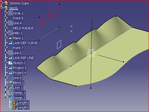
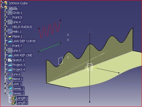
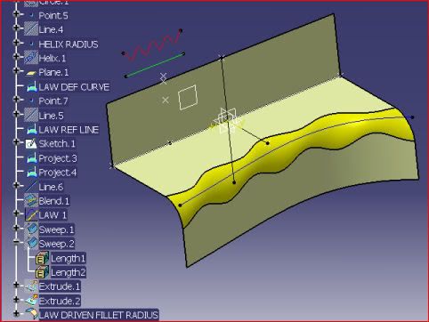
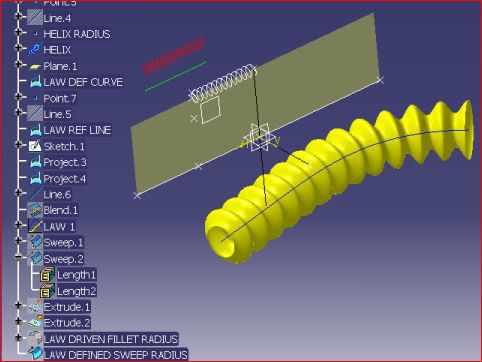
The following examples of Sweeps using laws should give some idea of what's going on; in each case I've used a sinusoidal curve, because it easily illustrates the effect, to create a law. The sine curve is made by normally projecting a helix onto a plane and positioning a reference line somewhere underneath it. The varying distance of the curve to the line is the 'Y' value at any point 'X' on the line.

The first picture shows a fixed length flange on a flat part, as the flange goes along, it's angle is changing relative to a plane (or surface). The 'Y' values of the law are being used as degrees.
Law-Angle01.jpg


The second picture shows another flange, this time it's at 90[°] to the part, but now, the same law is used to define a length - or height of the flange.
Law-Length02.jpg


The third picture is of another flange on the shaped edge of a part, the angle and length are both constant but this time the law is defining a radius of the corner fillet.
Law-Radius03.jpg


The next is a Sweep where the radius of the is corrugated hose is defined by a sinusoidal law.
Law-Sweep04.jpg


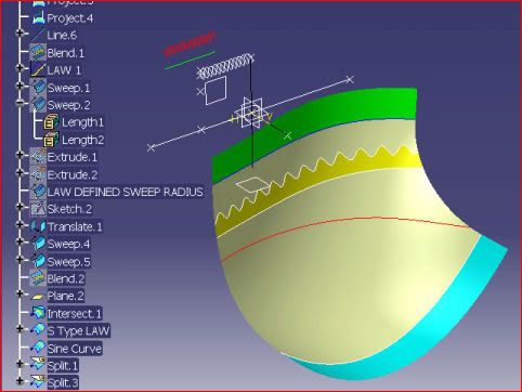
One last example shows a Parallel Curve (Offset would have been better than Parallel) where a 'S' type curve has been offset from a plane-cut thru' the surface and then the sine curve applied to that. The surface itself has two sweeps to act as tangency supports for it, one of the sweeps has a linear law to change the angle WRT to a ref. plane ; the other uses a 'S' type law. This a powerful tool in surfacing.
Law-Offset05.jpg


In some these examples I've tweeked the radius and pitch of the background helix, some of the pertinent elements in the Tree have been renamed to make this easier to remember.

All this is a taste of what can be done with Law, it is a very powerful function and well worth having some appreciation of.

Before V5, I think Law (used with Surf2), was more powerful, but it wasn't easy to understand at first, back in 1983 Catia V1 was nothing like it is now and I used Law a lot for surfacing, and for doing developments (flatwraps) of ruled surfaces - such as cut-outs in irregular cones. Law used to be able to handle areas - a typical application was an inlet duct, where the expansion of air in a duct had to be controlled in a user defined manner. All these things are just done in a different way now.

Apologies for the number of images, but I can't get clickable thumbnails to work on this forum, and I wanted the images to be open alongside the text.
 
What exactly are law curves and where else are they useful?

Laws are used to control features.

Simple example: fillets. By default, all fillets (in GS1, GSD, PartDesign) are created as linear constant. What does that mean? It means that they are the same size from start point to end point. Variable fillets, on the other hand, use a law to define the variation in the size of the fillet. A straight line would be used as the "reference". This would correspond (in some way - whether absolute or relative) to the length of the edge that the fillet is applied to. The "definition" would be the values of the geometry that you are trying to control. In the case of a variable fillet, it would be the fillet size.

The position of any point on the "definition" relative to the "reference" defines the size of the fillet (in our example) at a given point along the length of the selected edge. So, if your "definition" crosses over the "reference" line at a point that is 25mm from the end of a 100mm line, you would have a 0mm fillet at 25% from the starting point of your fillet. If the law is defined as absolute in size, it is easy to set up the exact numbers, as they correspond to part size. In other words, you can work with a law as a type of "blend", or you can precisely control where a feature will be created at a certain size.

On a 100mm line, place your start point at 1mm above the line. Place the end point at 5mm above the line. Apply the law to a variable fillet on a 100mm edge, and you will have a 1mm fillet at the start point, and 5mm at the edge. Easy, right?

Other types of laws exist. The basic laws are constant, linear, S-type, and complex. (where complex = user defined)

Law curves are useful anywhere you can't get the type of control you need elsewhere. Laws are also what makes the big difference between the GS1 and GSD workbench. For $8,000 extra, you get the set of law functions that otherwise turn your MD2 license into an HD2. They permeate through all of the surfacing functions. Surfacing is weak, and rather useless without this functionality, although you may or may not see it on the frontend.

Hope that helps you!

-----------------------------------------------------------
Catia Design|Catia Design News|Catia V5 blog
 
Kapitan and solid7,

Thank you both for the detailed law curve explanations, I gave you both a star. I really wish the both of you contributed to the Catia on line help, the paucity of information there is very disappointing.

Regards,
thixoguy
 
Well, thanks for the comments fellas, it proves that somebody actually reads all this stuff.

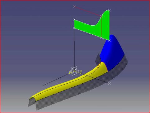
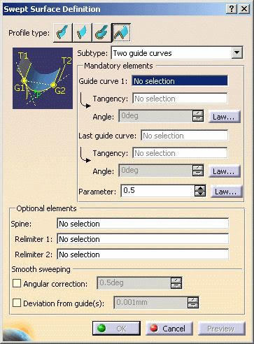
But, I'd forgotten one other Law that's used in surfacing: the Parameter that controls a Conic. It's a (non-dimensional) value - a ratio of where the conic vertex is WRT the tangent intercept. It defines a conic in SURF2 (pre-V5) and in the V5 Sweep: 2-Guides, 2-Tangents and a Parameter (Law). In the picture the Law is holding the surface in the elliptical range (yellow) for some time before passing momentarily through the parabola (red) and into the hyperbolic range (blue). These values have to be between 0 and 1, so the law is drawn with 'Y' values of 0 to 100 and the law scaling value 0.01 used - because I'm working in millimeters.

The Tensions in a Blend Surface can be controlled in a limited law manner (R14) but only as Constant, Linear and 'S' type.

Law-Parameter05.jpg


Law-Parameter05A.jpg
 
This is why I love these forums. Thanks guys.

Bob
 

You aren't obligated to do so, but it is a very good avenue for sharing complex descriptions, and an even better way of archiving frequently asked questions. That's exactly what I set it up for. Your contributions will/are much appreciated by all, myself included.


-----------------------------------------------------------
Catia Design|Catia Design News|Catia V5 blog
 
Status
Not open for further replies.

Part and Inventory Search

Sponsor