CaliEng
Structural
- Feb 14, 2020
- 49
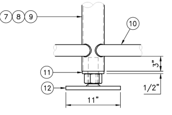
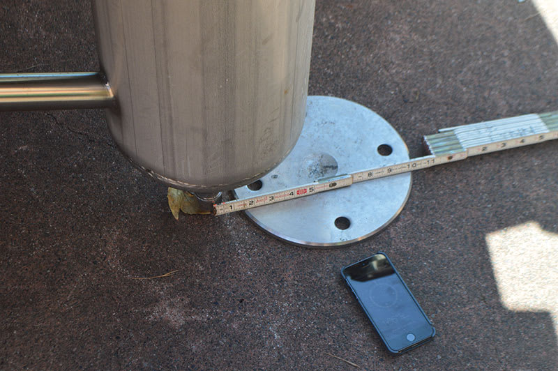
Seeking a bit of guidance on how to analyze the shear capacity of a threaded stud used as a baseplate connection for leg of equipment stand. Concern is that seismic lateral forces may shear off at the shreaded stud section (example in 3rd photo). I have the entire structure modeled in SkyCiv (Structural analysis software) and the anchor bolts modeled in Hilit Profis. But I want to look at one specific foot, and the shear going into the 2" threaded stud. You can see a couple reference photos for context.
PROFIS Shows sufficient anchorage.
The Skyciv shows an exceedence in material yield for this member section (circular 6" HSS) to solid 2" section).
However would a simple shear calc be applicable? (i.e. T = F/A (40kN/2026 mm2)) shows only 20 MPa
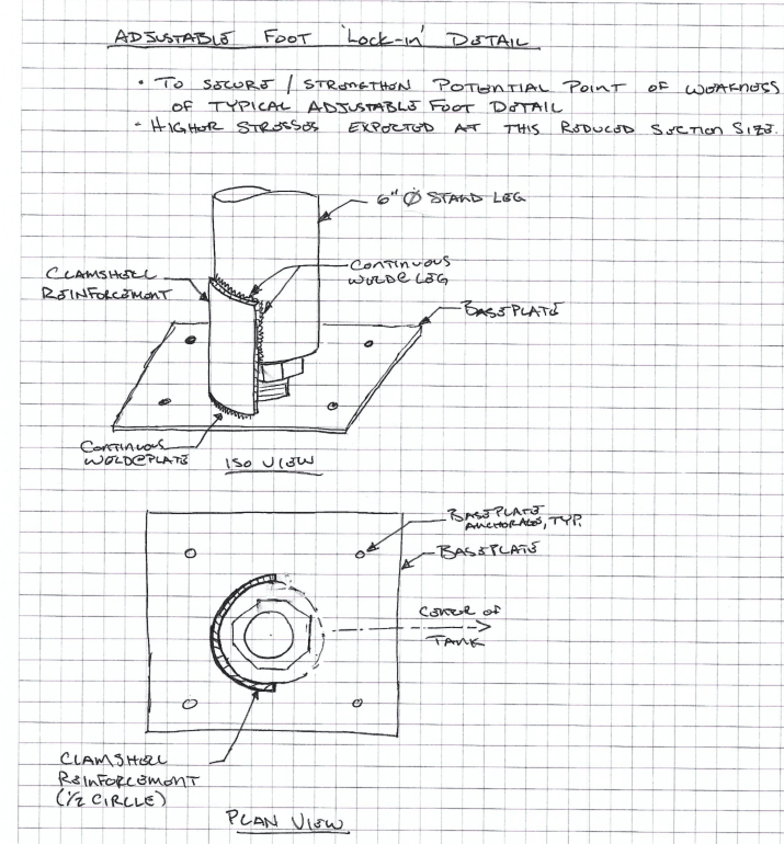
FYI due to the exceedence from SkyCiv i was proposing a reinforcing clamshell (2nd photo) but if this is not necessary, then save money/time.
Thanks for the guidance!
PROFIS Shows sufficient anchorage.
The Skyciv shows an exceedence in material yield for this member section (circular 6" HSS) to solid 2" section).
However would a simple shear calc be applicable? (i.e. T = F/A (40kN/2026 mm2)) shows only 20 MPa
FYI due to the exceedence from SkyCiv i was proposing a reinforcing clamshell (2nd photo) but if this is not necessary, then save money/time.
Thanks for the guidance!

