Continue to Site

Eng-Tips is the largest engineering community on the Internet

Intelligent Work Forums for Engineering Professionals

  • Congratulations waross on being selected by the Eng-Tips community for having the most helpful posts in the forums last week. Way to Go!

Metal Deck Diaphragm ASCE Wind Case 3 1

Status
Not open for further replies.

DayRooster

Structural
Jun 16, 2011
143
I have looked through the forum for guidance on this question but did not see this topic specifically addressed. If I did overlook a thread then please bring it to my attention:

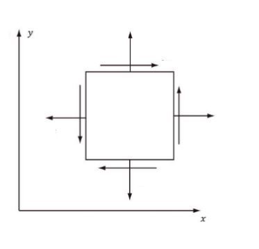
I am looking for some guidance or reference that describes in detail out how a metal deck diaphragm that is properly fastened to a building roof can address ASCE 7-10 Figure 27.4-8 Case 3. This wind case is to simulate wind at a diagonal to building. For my example, I have laid out a simple 80’x40’x20’ tall building (see attachment). I have also thrown in some basic loads for windward and leeward wind at the roof level on both sides. This is not a real life situation and is just an example as a talking point. Keep in mind I am asking this question because I traditionally use steel braces instead of a metal diaphragm to transfer loads to the vertical stability system. Generally, this has to do with the fact that the majority of the structures I work on are large industrial structures. I am curious more about metal deck diaphragms because I have seen many references that state that metal diaphragms are very commonly used. In my research I have seen only examples that show wind in one direction (along the long face of the building) but never the other side (short face) or on both sides. I have spoken to senior engineers at my work and they have stated that they do not know the answer to my question but did confirm that metal deck diaphragms are used in many industries. I look forward to anyone who can provide some clarity to this situation.
 
 http://files.engineering.com/getfile.aspx?folder=dd703d2d-8310-45de-93ab-7a6ebe78278b&file=Steel_Diaphragm_ASCE_7-10_Figure_27.4-8_Case_3.pdf
Replies continue below

Recommended for you

Wouldn't you just break your wind up into orthogonal components and look at each one independently in regards to load path into your bracing system?

Then add the two shears back together to get back to the effective shear in the metal deck for deck shear and deck fastening design?


Check out Eng-Tips Forum's Policies here:
faq731-376
 
At first that seems logical but I had some question marks about it:

- I am curious if this was what the SDI testing for metal decks is meant for a bi-axial load.
- How does the metal deck react to deflecting in two directions.
- Also, how does the perimeter beams and fasteners react when loads overlap since traditional the side beams take shear load while the top and bottom (chord) beams take tension or compression. When the load is in two direction these forces overlap which complicates the situation.

I guess I could design in both directions and keep the direct sum of the unity ratios under 1.0 but generally with steel the direct sum is overly conservative. I find it odd that all examples of this situation do not address this situation even though it appears commons based on ASCE wind requirements.
 
The people at the SDI are quite helpful. Their goal is to make you want to use their products. Give their tech department a call to discuss.
 
I am going that route too but I thought it would be best to hear from other design engineers in addition. I am curious how others are designing these types of buildings or potentially doing some kind of work around.
 
I'm north of the border but some people here will look at the 75% from each direction and keep the total diaphragm strength below 1. Some people ignore it outright.
 
I believe that it is just as simple as JAE has proposed above. Conventional diaphragm design considers the diaphragm to be resisting only shears, no axial or bending loads. As such, for each location on the deck being considered, you would work out the classic differential element shear forces for each component of load and simply superimpose the result. With the deck shears calculated this way, there really wouldn't be anything special about the bi-axial case from a design perspective. Therefore, no special testing or interaction equations would be necessary.

For what it's worth, I don't know that I've ever actually seen anybody design a diaphragm for the diagonal wind case. That's not to say that it shouldn't be done. It just doesn't seem to get done. You may well be on your way to becoming a pioneer of high quality diaphragm design. Of course, I practice in a technical backwater so... there's that.

I like to debate structural engineering theory -- a lot. If I challenge you on something, know that I'm doing so because I respect your opinion enough to either change it or adopt it.
 
Just remember that shear is essentially non-directional....think about your little square force/shear element:

Element_itjxsq.jpg


So any piece of deck within your diaphragm simply sees "shear".
But for load path into collectors and braces you need to break it down directionally.

Check out Eng-Tips Forum's Policies here:
faq731-376
 
Jayrod - That's kind of what I am seeing too; especially, the part about people ignoring it ;) Also, if that is the case I generally don't ignore things that are complicated or not well described...I usually find a creative way to work around it or avoid it outright.

KootK - I think the method JAE proposed is logical. I would be curious to see an example worked out. I question why SDI, Vulcraft, New Millenium, etc. would not have this as one of their example problems (unless I overlooked an example problem). I am hesitate because the SDI method values are reliant on testing done by SDI and the results are slightly black box (in my opinion). It already seems kind of odd to me that you can just place a metal deck spanning in either direction then go to some charts and lets say choose a 36/4 puddle weld pattern with 2 sidelaps and you get a shear value that is good for loading in either direction. It took me a while for me to just not get too detail orientated about that situation and just move past it and accept their results. As for the second part of your response, I am also curious if there is some provisions in IBC or ASCE that allows the wind load design to be simplified to only consider one direction at a time. I have noticed for the most part that these types of buildings that use this design are relatively short less than 60 feet and also about a 2 to 1 length to width ratio or less. That just might be a pattern that I am seeing that means nothing but I am curious if there is any benefit to simplifying either the wind loading or potentially relying on another means for wind load distribution along the short face (such as a steel beam or a precast concrete wall). Also regarding the pioneer of "high quality diaphragm design" that made me laugh :) I am far from it. I generally like to know what I am getting into with my designs so I can avoid structural engineering "gray" areas as I refer to them. Personally, I like to feel confident about my designs and point to solid references or examples. I guess in doing so AISC & ACI have seen their fair share of questions from me...I guess I will add SDI to that list too.

BTW, thanks for everyone's responses. It is helpful for me to critically talk it out.
 
DaRooster said:
I question why SDI, Vulcraft, New Millenium, etc. would not have this as one of their example problems (unless I overlooked an example problem).

I think that it's a tricky position for those folks to be in precisely because diaphragm design is a grey area, at least with respect to what individual consultant design practice is. I imagine that they want to show you enough that you'll know how to work with their products but not so much that you'd ever mistake their guidance for being complete and absolving you of the need to exercise your own judgement.

If you ever have a hankering to get a sense for just how deep this particular rabbit hole goes, consider procuring a copy of the book referenced at the end of this article: Link. It's for wood diaphragms but most everything is applicable to steel deck as both utilize the same shear panel philosophy. Unfortunately, once you've seen it, you can't really unsee it. Prepare to either hemorrhage fees or relax your stance on avoiding grey areas.

I like to debate structural engineering theory -- a lot. If I challenge you on something, know that I'm doing so because I respect your opinion enough to either change it or adopt it.
 
KootK - I will definitely look into that book. I am still curious if there is a response beyond use engineering judgment which if that is the case then I guess I will have to accept it. Luckily in my line of work it mainly deals with large open industrial structures that require steel braces horizontally and vertically for stability. Which in this situation I guess is beneficial since I don't have the fear of hemorrhage fees versus relaxing my stance on avoiding these situations [thumbsup2]. Most small enclosures we use are PEMB which employ a different system for structural stability since the roofs are standing seem. I just like to get ahead of things in case these odd cases pop up and I will have an idea of the direction I would like to take from the start.

JAE - I am following your logic. I threw together a basic loading layout to see if you had any more thoughts. I assumed that the vertical bracing is along the perimeter in both directions. I added color this time to make it clear. Purple is the deflection (scaled up for clarity), Green is the loading on the long face along with chord reactions, Blue is the loading on the short face along with chord reactions. The red clouds are corner areas that appear to have local load concentrations. What are your thoughts?

Thanks again!

 
DaRooster,

Assuming a 200 ft. x 100 ft diaphragm.

Total E-W shear (perp. to the 200 ft. side) = 300 plf x 200 / 2 / 100 ft = 300 plf shear on diaphragm side along N and S sides.
Total N-S shear (perp. to the 100 ft. side) = 300 plf x 100 / 2 / 200 ft = 75 plf shear on the diaphragm side along the E and W sides.

Shear in the corners (where your red clouds are) - shear added together directly = 375 plf.

Now look at the singular direction of wind (Case I) -
(300 plf)/0.75 x 200 ft. width / 2 / 100 ft collector = 400 plf > Case III wind shear (375 plf) in terms of diaphragm shear.

So for the diaphragm - in this case, it may not ever have Case III controlling for diaphragm shear.

For other irregular buildings that may not be the case.

Check out Eng-Tips Forum's Policies here:
faq731-376
 
JAE - That is very interesting...it appears you have found a conservative way to neglect Wind Load Case III as long as the building shape fits within those parameters. For example this situation does work for a square 200' x 200' building but does work for a 200' x 100' building. I am going to think about it some more but I think you might have provided the insight I was overlooking. Thanks again!
 
DaRooster - it may be that Case III is meant more for irregular buildings where a non-orthogonal wind direction might stress certain structural elements more than in the orthogonal cases.

A good example (I think) might be this situation - a very interesting case technically as well as ethically: Case Study - The Citicorp Center Design

Check out Eng-Tips Forum's Policies here:
faq731-376
 
I will second KootK's point about once you see the book (by Malone) you can't unsee it.

The amount of questions I have asked about diaphragm design and the amount of silence I have received from experienced engineers is very interesting.
Makes me wonder why I do the calcs... (no one else seems to), but it makes me feel good to be able to put a number to important items rather than just guessing.

 
Status
Not open for further replies.

Part and Inventory Search

Sponsor