Tek-Tips is the largest IT community on the Internet today!

Members share and learn making Tek-Tips Forums the best source of peer-reviewed technical information on the Internet!

  • Congratulations TugboatEng on being selected by the Eng-Tips community for having the most helpful posts in the forums last week. Way to Go!

Measurements with Pins ANSI B92.1

Status
Not open for further replies.

WendelTrento

Materials
Joined
Jul 23, 2020
Messages
13
Location
BR
Dear friends,

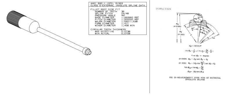
I'm having difficulty sizing the gear profile according to the attached table.
Could someone help me how to calculate the diameter of the pin and the distance between them? and what tolerance to apply to the values.
 
 https://files.engineering.com/getfile.aspx?folder=0c6c4759-1a83-4e3c-aa9f-72faf82c1ede&file=Annex.png
You should post graphics in line so that people can see them rather than go through the trouble of downloading and then accessing the file.

Annex_blcxij.png
 
Presumably the manual that this is copied out of explains the procedure you need to use.
This tool is commonly used as a go-no-go gauge for gear teeth.
Although you have the equations you need to find the measurement for "any" involute tooth arrangement, the manufacturer of the pin probably publishes a table that would be much easier to use. Just get the table from the gauge manufacturer and make your life easier.
 
WendelTrento

max effective is the go size of a ring spline gage
min actual is the no go size of a spline ring gage.
What is the quantity, if a large quantity spline gages need to be order from a certified spline gage company.
max effective can not be measured with wires, obtain the specification and look up the minimum plus the specified tolerance from the specification.= the maximum actual. not the same as maximum effective.
the measurement over wires can be calculated from this. to ease the pain contact a gear manufacturing company to assist.
 
Status
Not open for further replies.

Part and Inventory Search

Sponsor

Back
Top