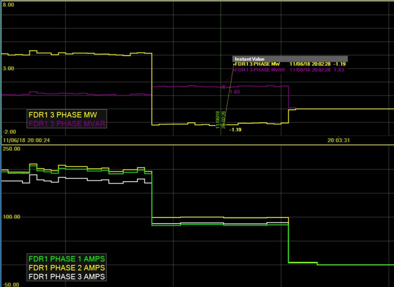
For those who have briefly paralleled separate feeders for one reason or another, what were the typical tie currents seen?
As a power system operator, I've been doing this for years...and the answer is, as so often in engineering, "It depends."
I've seen transfer currents of almost zero amperes when going into parallel, typically when the two feeders share sources of virtually equal impedance; indeed it has happened that only when adjusting the ULTCs at either end of the parallel to move the null point to the device at which parallel is to be broken that actual changes in the supplying feeders' currents have been observed [ the general idea during load transfers is to have minimal reactive flow through parallel breaking devices ].
I have also seen [ unintended! ] flows of several hundred amperes, and at 44 kV, no less, when parallel has been made...
A good place to start is the almost-so-obvious-I-shouldn't need-to-say-it rule for load transfers that the load sharing between two paralleled feeders typically varies inversely as the impedance of the two supplies. I'll often see this when paralleling between one Dual Element Spot Network [DESN] station fed via two 125 MVA transformers and another with 83 MVA banks. There are occasions when, upon going into parallel, one of the two stations will "hog" the load, perversely often enough when the desire is to transfer the load in the other direction. In such cases we commonly unload one of the "hogging" transformer secondary windings by opening its circuit breaker so as to reduce the transfer through the parallel-breaking device to within its safe break capability. Sometimes we also do it just to reduce the voltage excursions experienced by our customers during switching operations.
when paralleling low-tension feeders between stations supplied at different system voltages [ in our case, generally between 115 kV and 230 kV supplied stations ], we almost invariably unload one secondary winding at the 230 kV station before even going into parallel.
Added via edit: When planning load transfers we also strive to ensure the high voltage grid level loop between the two stations to be paralleled won't be unduly long, as otherwise ugly phase angles can develop that will make stuff go boom and let the smoke out. In Hamilton, Ontario, for example, we have two stations that are fed from a pair of 115 kV circuits that are normally fed radially from two separate 230 kV stations via 230/115 autotrafo's, so if an LT parallel between two of the stations on opposite sides of the normally open 115 kV point is being planned we make arrangements to alter the HV system configuration as needed [ we have various options at our disposal ] so as to have both of the paralleling substations on the same 115 kV supply.
A relatively recent development is that with the advent of more and more distributed generation on our feeders, we have one more tool, namely generation dispatch, available to assist with adjusting flows prior to the breaking of inter-feeder parallels.
Hope this helps.

