axym,
I was specifically addressing a simple cylindrical surface arc. I agree regarding other curved surfaces, but:
The so-called "orientation" of an arc in the view where its curvature is visible relative to a datum plane parallel to the axis of the theoretical geometry is not able to be "duplicated by translation", it can
only be caused by translation.
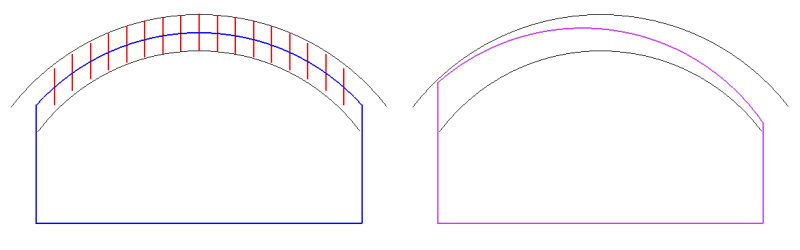
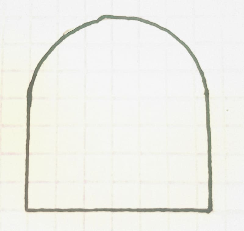
Consider a modified figure of that part where the side surfaces are initially tangent to the arc at both sides as the graphic below attempts to show.
There is clearly no orientation relationship between the arc and the datum derived from the bottom surface: as long as there is tangency at both sides and assuming that the two vertical side faces are parallel and vertical, the imaginary line (2D description for clarity) that could connect the tangency points can only be horizontal. You are unable to rotate the arc to appear inclined. There is as much "orientation" relationship as there would be between a full cylinder and a plane parallel to its axis, at the rotational DOF about the direction of the axis of that cylinder.
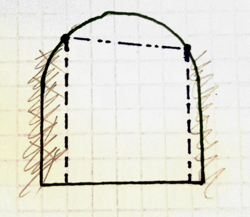
Now consider that the tangency is canceled and the vertical side faces are adjusted to create corners where they connect with the arc - this could be achieved by removal of material from both sides. The new side faces are shown dashed:
All of a sudden the arc looks like it could have all sorts of orientations, one of which is shown. That already looks fishy because the relationship between the arc and the datum derived from the bottom face didn't change, it is only the side faces that were modified. We can ignore that fishiness but only until we try to analyze the difference between the original condition of tangency and the modified version: the axis of the theoretical arc was initially centered to the center plane between the vertical sides. In the modified version, it is no longer centered. If it is so, what looks like an "inclination" is actually translation of the axis of the theoretical arc relative to the center of the width.
chez311,
chez311 said:
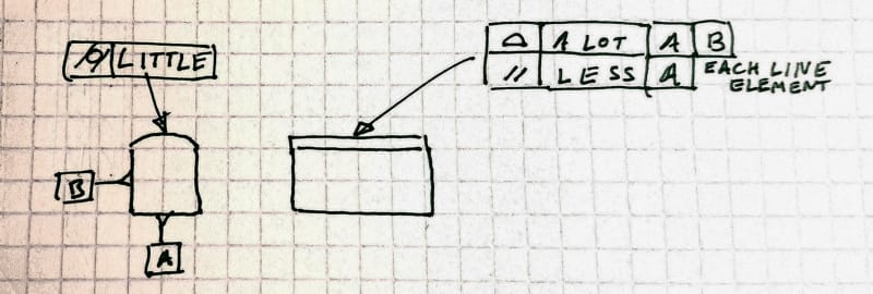
It would also impose different levels of form control.
I don't think that parallelism of each line element controls form at all. The feature could be produced not arc-shaped and still conform to the parallelism of line elements requirement. In this scheme, only the cylindricity requirement is the final word regarding form. The profile FCF could control the form if it wasn't for the cylindricity tolerance. The composite tolerance is not much different in the sense that only the last datum-less segment is the final word regarding form. The insignificant difference is that in the composite profile case, each segment could control form if there were no subsequent segments. But that is only a hypothetical analysis that doesn't affect the end result - the form is controlled with the "LITTLE" tolerance value in both options.