Eng-Tips is the largest engineering community on the Internet

Intelligent Work Forums for Engineering Professionals

  • Congratulations waross on being selected by the Eng-Tips community for having the most helpful posts in the forums last week. Way to Go!

Limit on second-order moments

Status
Not open for further replies.

Settingsun

Structural
Aug 25, 2013
1,513
AU
ACI 318-19 clause 6.2.5.3 limits the bending moment from second-order analysis to a maximum of 1.4 * the moment from first-order analysis. Is this referring to the respective maximum moments which may be at different locations along the column, or to moments at the same location along the column (ie maximum moment location in 2nd order analysis)?

Screenshot_20211222-003945_Adobe_Acrobat_x0ho4e.jpg
 
Replies continue below

Recommended for you

I feel as though the most technically correct application of the limit would be to ensure that, at no location, does the second order moment at that location exceed the first order moment at that location by more than a factor of 1.4. In my mind, this best captures the spirit of the thing which, I believe, is to limit rampant moment amplification arising as a result of excessive column slenderness.

I can see how what I just described would be difficult to implement in routine practice however. I suspect that the more common implementation is to make the comparison between:

a) Max first order moment occurring at any location and;

b) Max second order moment occurring at any location that need not be the same location as [a].

As an aside, in practice, I've found that it takes a fair bit to generate slenderness problems in a meaningfully double curvature column.
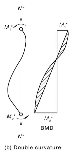
 
The technically-correct interpretation occurred to me but that would constrain the point of zero moment to not moving between first and second order analyses if applied strictly. I've never actually paid attention to the zero point but suspect it does move.

The common implementations you mentioned is how I can see it tallying with the moment magnifier for braced columns. C_m < 0.6 for reverse curvature so you need the denominator part of the magnifier to be less than 0.6 also to 'break even'. That could be quite slender/floppy. As you say, it's hard to get reverse curvature to have slenderness problems.

Then I wonder whether it's actually meant to apply to braced columns. The commentary refers to the Q coefficient which is a sway thing. The Australian code limits the sway magnifier to 1.5 but no limit on the braced magnifier.
 
steve49 said:
The technically-correct interpretation occurred to me but that would constrain the point of zero moment to not moving between first and second order analyses if applied strictly. I've never actually paid attention to the zero point but suspect it does move.

Yeah, that's the main issue I have with KootK's interpretation. I don't think it's completely wrong. I just think the idea of the inflection point moving would be subject to some engineering judgment....

Therefore, I'd prefer the more common interpretation.
 
My beef with the common interpretation for the case of a braced, double curvature column is that, per steveh49's sketch, you would seem to have to absorb rather a lot of moment application within the member before your ratio would even get higher than unity.

steveh49 said:
Then I wonder whether it's actually meant to apply to braced columns.

I was wondering the same as I was typing my initial response.
 
steve49 said:
Then I wonder whether it's actually meant to apply to braced columns.

I like to think of this in terms of P-Big Delta and P-Little Delta.

So, M1 and M2 in Steve's diagram would be the initial moments at the ends of the member. Because these are not amplified at all, this implies that P-Big Delta is zero (or very close to it).

For a true moment frame structures, I think the "common interpretation" is almost guaranteed to be the correct one. You'd have to have a pretty slender column for the P-little delta effect to dominate over P-Big Delta.

Now, to give a physical interpretation for Steve's diagram: I'd say that this is a moment frame frame within a structure where the main lateral resistance is from a braced frame or shear wall.

For these cases, I think the intent is more like the Q factor (from ACI) or the Theta factor from ASCE 7 where you are not so much directly amplifying moment (like in a FEM analysis), but rather calculating a "stability index" type of value that represents 2nd order amplification.
 
Status
Not open for further replies.

Part and Inventory Search

Sponsor

Back
Top