Tek-Tips is the largest IT community on the Internet today!

Members share and learn making Tek-Tips Forums the best source of peer-reviewed technical information on the Internet!

  • Congratulations cowski on being selected by the Eng-Tips community for having the most helpful posts in the forums last week. Way to Go!

Learning Structural Connection Types – Pin vs Fixed (Real World Example)

rpand4

Civil/Environmental
Joined
Jun 20, 2011
Messages
24
Location
AU
Hey everyone,

I’m currently brushing up on structural engineering concepts, especially around connections, and I thought I’d share something I’ve been analysing to get better at spotting connection types in real-world structures.

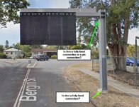
The attached photo is of an overhead sign structure that I see everyday. The sign is advertising height restriction to a bridge. I’ve been trying to work out what type of connections are used, particularly:

  1. The base connection of the post — is that a fully fixed connection?
  2. The connection between the vertical post and the horizontal member — pin connection or fully fixed?
From my understanding:
  • A fully fixed connection resists moments, shear, and axial forces, keeping angles between members constant under load.
  • A pinned connection resists only shear and axial forces but allows rotation, meaning angles can change under load.

Looking at this sign, I’m thinking:

  • The base connection likely needs to resist significant moment from wind loads acting on the sign, so I’d suspect it’s designed as a fully fixed connection — but I can’t tell just by looking at the flange and bolts. Am I correct?
  • The post-to-beam connection looks like it has stiffening plates, but would that realistically provide full fixity? Or is it designed to allow some rotation, acting more like a pin?
Thanks for your help in advance.

Connection Type.jpg
 
Your understanding of the concepts is generally correct. The best thing to do in these cases is to draw a free body diagram of your frame. What loads do you have acting in the X and Y directions (and Z if you want to get fancy). What reactions do you have in each of those directions? Now, sum your forces and moments. If things aren't balanced, you know you have something messed up somewhere, and go back and reconsider what you assumed as your connections and boundary conditions.

In this case, what do those connections need to do in order to maintain stability for the sign?
 
Designed as fixed. In reality, not fully fixed, but close enough.
 
Designed as fixed. In reality, not fully fixed, but close enough.
What is the tell tale sign that tells you it is a fully fixed - or close enough? Is it the stiffener plates? I am trying to train my eyes to distinguish between connection types.

Thanks for your response
 
It would lean if it wasn’t fixed.

In terms of details, bolts positioned outside the section to provide large lever arm to resist bending force within the connection, as well as stiffener plates
 
It would lean if it wasn’t fixed.

In terms of details, bolts positioned outside the section to provide large lever arm to resist bending force within the connection, as well as stiffener plates
This makes sense. Thank you so much!!!
 
your example is simpler than that. The horizontal arm is a simple cantilever, and so statically determinate. whether is is fixed or partially fixed is up for grabs, but it cannot be pinned. the base of the cantilever will react the required moment, where it does so with negligible deflection (fixed) or with significant (noticeable) deflection (partially fixed) is something to be determined.
 
I'm with rb1957.... You KNOW that both connections were designed as fixed connections because they're both cantilevers.

I'll quibble with some language here:
1) In reality all real world connections are somewhere between fixed and pinned.
2) AISC tends to use the terms "fully restrained" and "partially restrained" to differentiate between moment connections that are a pretty rigid (i.e. fully restrained) and ones that allow more rotation. This is described well in the AISC 16th edition figure 11-1 and the accompanying discussion.

To address your question . comment about "stiffener plates", yes stiffener plates would tend to be indicative of a FR (i.e. Fully Restrained) moment connection. However, they are not a requirement.... which is probably one reason why AISC 358 requires that the pre-qualified moment connections comply with the limits set up with actual testing.

Honestly, that whole chapter in the AISC manuals is EXCELLENT reading if you want to understand steel moment connections better.
 
Since your column is a W-shape (I-shape), the anchor bolt location that "restrains" the flange is an indicator it is fixed. Had they wanted it to be pinned, the anchor bolts may be located in between the flanges closer to the center of the web. The fact the entire structure is unstable UNLESS the base is fixed is another indicator.

Spend some time studying existing standard connections of known fixity and see what they have in common. That will teach you a lot. Tube and Pipe are harder to distinguish at times, but I-shapes are much easier. Is the cantilever arm a tube? Envision pinned as a door hinge and fixed as a diving board. Neither is a perfect example but it gets you started. Try attaching a diving board with a door hinge and you will never worry about having an Olympic diving competition at your pool.

Fully versus partially fixed is more a reality of life than something we all thought we would create. It is how we cope with the imperfections in our concepts of fixed or pinned. To me, fixed can be closer to achieve than pinned.
 

Part and Inventory Search

Sponsor

Back
Top