Hey everyone,
I’m currently brushing up on structural engineering concepts, especially around connections, and I thought I’d share something I’ve been analysing to get better at spotting connection types in real-world structures.
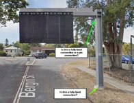
The attached photo is of an overhead sign structure that I see everyday. The sign is advertising height restriction to a bridge. I’ve been trying to work out what type of connections are used, particularly:
Looking at this sign, I’m thinking:

I’m currently brushing up on structural engineering concepts, especially around connections, and I thought I’d share something I’ve been analysing to get better at spotting connection types in real-world structures.
The attached photo is of an overhead sign structure that I see everyday. The sign is advertising height restriction to a bridge. I’ve been trying to work out what type of connections are used, particularly:
- The base connection of the post — is that a fully fixed connection?
- The connection between the vertical post and the horizontal member — pin connection or fully fixed?
- A fully fixed connection resists moments, shear, and axial forces, keeping angles between members constant under load.
- A pinned connection resists only shear and axial forces but allows rotation, meaning angles can change under load.
Looking at this sign, I’m thinking:
- The base connection likely needs to resist significant moment from wind loads acting on the sign, so I’d suspect it’s designed as a fully fixed connection — but I can’t tell just by looking at the flange and bolts. Am I correct?
- The post-to-beam connection looks like it has stiffening plates, but would that realistically provide full fixity? Or is it designed to allow some rotation, acting more like a pin?

