Continue to Site

Eng-Tips is the largest engineering community on the Internet

Intelligent Work Forums for Engineering Professionals

  • Congratulations MintJulep on being selected by the Eng-Tips community for having the most helpful posts in the forums last week. Way to Go!

Learning how to calculate secondary moment using Bruhn's

oriolbetriu

New member
Jun 26, 2024
12
Hi!

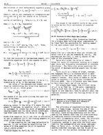
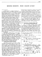
I am trying to learn how to calculate secondary moment, so that I can analize properly any strutted wing. I am following Bruhn's example, please see pages below. I think that I understand, the way the formulas are deduced from the force diagram, which ends up in a secondary order differential equation;

d^2M/dx^2 + 1/J^2*M = W

Which can be rewritten as;
d^2M/dx^2 + 1/J^2*M - W = 0
or;
y´´ + 1/J^2 + 1/J^2*y - W = 0

Solving this equation is sort of trivial. Because the roots of the differential equation can be solved, as if the equation was a second degree polinomy;
(-b +-(b^2 - 4*a*c)^(1/2))/(2*a) = (-(1/J^2) +-((1/J^2)^2 - 4*1*W))^(1/2)/(2*1)

If we look inside the root the value is positive, because (-4)*(-W) is positive, therefore the solution ought to be in the form of;
M = C1*e^(r1*alfa) + C2*e^(r2*alfa)

However Bruhn gives as the solution of the differential equation, the form that is used for imaginary numbers;
M = C1*sin(x/j) + C2*cos(x/j)

How is that so?! I can not tell what I am missing? I am stuck with this, and unable to advance. I never finished my aero studies, and I do not know anyone in my close circle, with whom I can discuss such things.

Any advice will be greatly appreciated!

Oriol

Bruhn 1.pngBruhn 2.png
 
Replies continue below

Recommended for you

I still have the book recommended back when I was at uni. For a pin ended column, the 2nd order diff is
uyy + k^2.u = 0
The general solution is
u = A.cos(k.y) + B.sin(k.y) where k = (P/EI)^1/2
For beam column type problems, I’ve always seen this given as the general solution, followed by solving for the particular integral (additional terms as functions of the independent variable, in this example y).
 
Last edited:
Bruhn does not usually show all of his work. The point usually isn't to demonstrate a proof but only to illustrate principles. At a guess, Bruhn is using a trig identity in the differentiation. As a frequent user of Roark and Bruhn, I've noticed these derivations are normally solved with trigonometric functions, not exponential ones. School was too long ago for me to remember why. Someone more familiar with the methods to derive these solutions such as those in Roark can answer in detail (you might not find them here).

Also, not exactly sure why you referred to "imaginary numbers" but just in case you were taught to use "j" for your imaginary unit, in this context it doesn't mean that. You can find "j" as the square root of EI/P, none of which are negative. In Figure A5.66, the P vector is inward, making compression a positive value. No negatives under the square root, therefore no imaginary numbers.
 
Bruhn is a great resource but it is not a textbook, it is a reference work. In my ancient copy of this book https://www.sciencedirect.com/book/9780340719206/strength-of-materials-and-structures it is chapter 20, but in the new one chapter 18.
If you look in google books for

Strength of Materials and Structures​

By Carl T. F. Ross, The late John Case, A. Chilver

it is section 18.9
 
Blasphemer !

I'm used to the trig solution to the diff equation.

I'm not 100% sure I'd use that to solve a strutted wing, but there could be application for it.

For myself, the wing is pinned to the fuselage, and the strut reacts the root bending moment and the rest is pretty easy calcs. Sure I'm making assumptions but they seem pretty defensible to me. I don't recall OEMs doing it much different (albeit from 70+ years ago).
 
May be relevant... shed light on...this topic...
AFFDL-TR-69-42 Stress Analysis Manual

NOTE. 'Texts' teach... 'Manuals' are for quick/consistent working reference/calculations.
 
Rb. The inboard portion of the spar works as a beam column. However the error relative to a pure linear analysis is probably not that large if the spar is sufficiently stiff in bending.
 
Sure, there are many interesting things happening, a nice shear lag problem ... the strut adds it's compression load on (or below) the lower surface, the fuselage attachment is usually on the upper surface
 
I have seen real-world secondary bending [secondary moments?] that 'was unintentionally designed-in'.

I was lead engineer for a small jet. The flange of a spar chord notoriously cracked along the Spar-cap-to-web fillet radius @~7000-Hrs... adjacent to the root lugs. This was OK for the original requirement flight hours requirement ~7000-Hr... NOT good-enough to meet a new service life requirement for 15,000. Hmmmm.

I discovered the centroidal axis of the upper and lower spar caps were miss-aligned with the transverse axis of the 0.875 Dia shear-bolt [hole] at the root-lugs.

The misalignment was 'only' ~0.050 between the bolt and the spar cap at the lug holes... but these spar-cap loads at +/-6G was ~100,000# [rough number]. SSsoooo...

100,000# X 0.05-in = -/+5000in# unaccounted-for at the spar-cap at the root... which was unaccounted for in the stress analysis. In this case the moment added to the flange tensile stress was 'away from' the cracking spar flange.

Believe it or not, I solved the secondary bending issue to practically zero, by taper-shaving-off spar-cap material over a long taper [15-in]. This re-aligned the spar-cap load centroid, so it passed thru the BOLT centroid. The slightly higher spar cap stress, was overall less than with NO secondary bending... which stopped the flange from cracking.
 
Just to clarify, are you only interested in the secondary bending moment specifically? Not to be pedantic, but what Bruhn works down to is the location and magnitude of the maximum moment, or the formula for the moment at and point along the span. But these would be for the total moment due to all effects (applied lateral loads, couples, or eccentricity of the axial loads. So are you just trying to find a solution for the total moment due to all combined loads, or are you trying to isolate the contribution of the eccentricity in the axial load?

As mentioned, Bruhn is very useful but the "derivations" are often light and if you don't take it at it's word, you need to look elsewhere.

If you look just below Table A5.1 you can see the following references:
  • "Airplane Design" by Niles and Newell which is a classic book I recommend reading anyway
  • NACA T.M. 985
Furthermore, I will personally note that "Theory of Elastic Stability" by Timoshenko and Gere might also be useful here. Straight from Chapter 1, the differential equations for beam-columns are covered. Section 1.5 is specifically for a continuous lateral load on an axially compressed beam-column which seems to match your example from Bruhn A5.25 but in more detail.

I think these references can be found pretty easily.

In your problem statement you reference a strutted wing. So I'll also point out that we should be careful of the treatment of the structure depending on what you are dealing with. There is a bit of nuance... sometimes things like struts or connecting rods are analyzed for compression assuming some tolerance on the alignment of the endpoints. There is a bit of a difference between compressing something at an assumed initial angle and eccentrically compressing something that is straight.
 

Part and Inventory Search

Sponsor