milkshakelake
Structural
- Jul 15, 2013
- 1,179
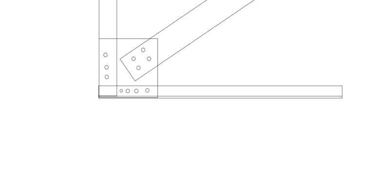
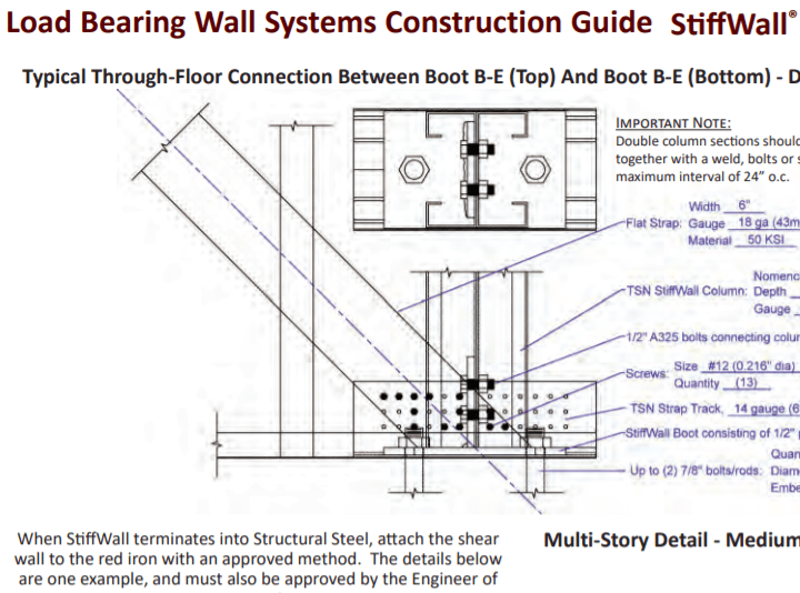
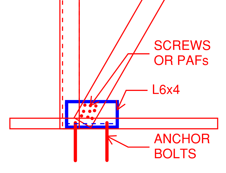
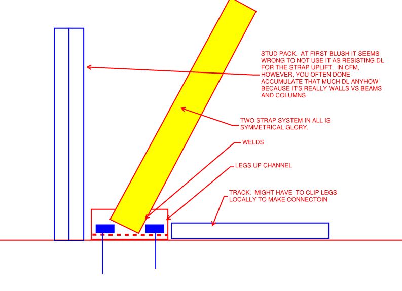
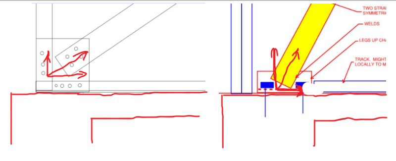
If I use a holddown with cold formed steel diagonal straps, there will be uplift and shear. The holddown schedules from Simpson only show tension/uplift capacity, not shear. How do I know if the shear is okay?
Wood is different because the plywood shear wall will take the shear and transfer it into the bottom plate, which can transfer it into the foundation with anchor bolts. I called Simpson about this but got bounced around between different "experts" so I'd rather ask here.
Wood is different because the plywood shear wall will take the shear and transfer it into the bottom plate, which can transfer it into the foundation with anchor bolts. I called Simpson about this but got bounced around between different "experts" so I'd rather ask here.