Continue to Site

Eng-Tips is the largest engineering community on the Internet

Intelligent Work Forums for Engineering Professionals

  • Congratulations waross on being selected by the Eng-Tips community for having the most helpful posts in the forums last week. Way to Go!

Lateral Instability of slender precast beam 3

Status
Not open for further replies.

struggle67

Structural
Mar 29, 2013
116
Hi,

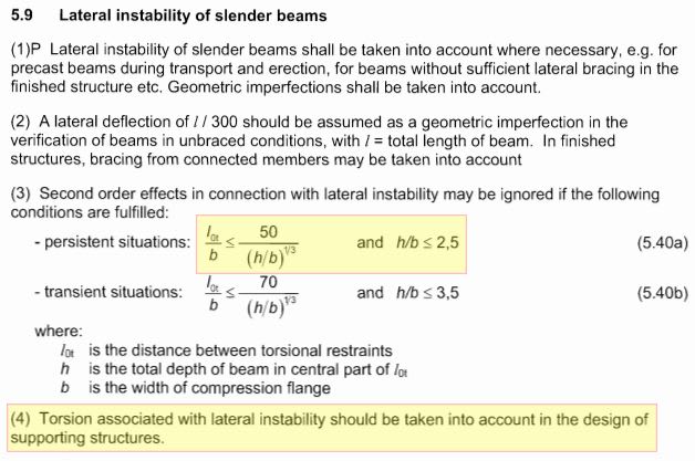
I have a very slender precast beam. And I have to check lateral instability (LTB). I know how to account for it in a steel beam design according to EC3 but I do not know how to account for it in a very slender reinforced concrete beam. I couldn't find any guideline in EC2. The screenshot below is from EC2 and that's all I could find.

Capture_er0ti6.jpg


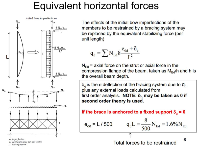
I am thinking to use this concept below which we normally use to calculate lateral restraint force required to prevent LTB for steel beams and get the equivalent lateral load. I will multiply that lateral force with an eccentricity (distance from C.A of the beam to the top compression face)to get the torsion. Then I will just either design the beam for that torsion or provide lateral restraint. May I know if my approach is logical & correct or is there any other way to do it? Thanks in advance for your help.

Capture1_mcmtyr.jpg
 
Replies continue below

Recommended for you

I don’t have an answer but I’m signing in here to hear some pearls of wisdom from our learned friends!
 
AS3600 will tell you for simple supported or continuous beams, the distance L1 between points at which lateral restraint is provided shall be such that L1/Bef does not exceed the lesser of 180*Bef/D or 60.

 
This is knowledge from the ancients. Equations 1 and 2 are still in the Australian building and bridge codes as per Trenno's post although #1 is tightened a bit in the building code (AS3600), but not the bridge code (AS5100). Bear in mind that there's an assumption on the ratio of E:f'c in the equation for Mcr based on 1960s concrete so probably take f'c = 30 MPa max regardless of what actual f'c you're using.

If the concern is stability during lifting, then there's potentially a reduction to this capacity to be taken into account because the ends of the beam aren't fully restrained against twist.

Concrete_beam_buckling_w1hnjn.jpg
 
SteveH raises an important point -- is your concern during service, in a condition with permanent (if widely spaced) bracing elements?

If so, your general approach seems logical. Be careful of combined stresses cracking your flange tips in some conditions.

However, if you are concerned with stability during handling, transport, erection, etc, that's a very different problem to solve. You'd want to start by reading the excellent papers by Mast.

----
just call me Lo.
 
The equations for LTB in places like Roark's are still applicable. You just have to be aware that these are ultimate buckling values. (I.e. a safety factor is warranted. For LTB, I've typically seen SFs of about 2 or 3 used.)

One concrete text I have takes on this subject: 'Reinforced Concrete Structures', by: Park & Paulay. (Published 1975, p.113-117) If I am not mistaken, Steveh49's pic is from that text.

They lean heavily on W.T. Marshall's work (source "4.9" in Steveh49's post):

W.T. Marshall, "A Survey of the Problem of Lateral Instability in Reinforced Concrete Beams," Proceedings, Institution of Civil Engineers , Vol. 43, July 1969, pp. 397-406
 
Hi Steveh / Lo
Thanks
My concern is stability during lifting. My beam section is U shape but solid at both ends 2 m long (like a cube) so I guess I should have sufficient rotational restraint at the ends.

Hi WARose,
Thanks for the references.
 
Marshall changed the 160 factor in the Mcr formula to 140 after receiving feedback/clarifications on one of the sets of tests the formula was developed from. This is in the 'discussion on' Ref 4.9 published a few months after Ref 4.9.
 
It might be worth consulting clause 6.6.3.3.4 of CEB-FIP model code 1990. Note that this is an old version of the model code.
 
Hi bkal,

Thanks

I had a look at the clause you mentioned. I have a few doubts. Hope that someone can give me a lecture [upsidedown][bigears].

- FIB clause recommends torsional stiffness GJ to correspond to the depth of the compression zone under the first-order moment but for Tr(torsional cracking moment), I will be using the whole section (full depth) resistance as flexural cracking does not affect Tr. Is it ok?

- In equation (6.6-35) why do I need to divide Qd(e2,adm+e) by π (Pi)?

- Although I am quite curious about how they derive this e2 (second-order deflection), I guess it will be lengthy and I will just use it as it is.

- For your easy reference, I have included a screenshot of the fib clause formulae below.

Capture_owcozv.jpg
 
Status
Not open for further replies.

Part and Inventory Search

Sponsor