Tek-Tips is the largest IT community on the Internet today!

Members share and learn making Tek-Tips Forums the best source of peer-reviewed technical information on the Internet!

  • Congratulations JAE on being selected by the Eng-Tips community for having the most helpful posts in the forums last week. Way to Go!

Lateral bracing to top flange of WF via friction clamps @ 12" centers 3

Status
Not open for further replies.

Ingenuity

Structural
Joined
May 17, 2001
Messages
2,374
Location
US
I have a temporary construction access platform on a project site consisting of a pair of parallel W8 beams approx 20 feet apart, and alum-beam joists span transversely to (and supported by) the W8's on the top flange. The W8's are 35 ft long - continuous spans - with a max span of about 14 ft.

The W8's are currently laterally braced to adjacent concrete columns and walls at about 10' centers; BUT for one of W8's all the lateral bracing has to be removed to accommodate a revised work sequence. The other parallel W8 lateral bracing shall remain.

I am trying to justify the adequacy of the alum-beam joists @ 12" centers (that sit on the top flange of the W8's) to laterally brace the top flange of the soon-to-be UNbraced W8 and take the force back to the other W8 that is adequately laterally braced to rigid concrete columns.

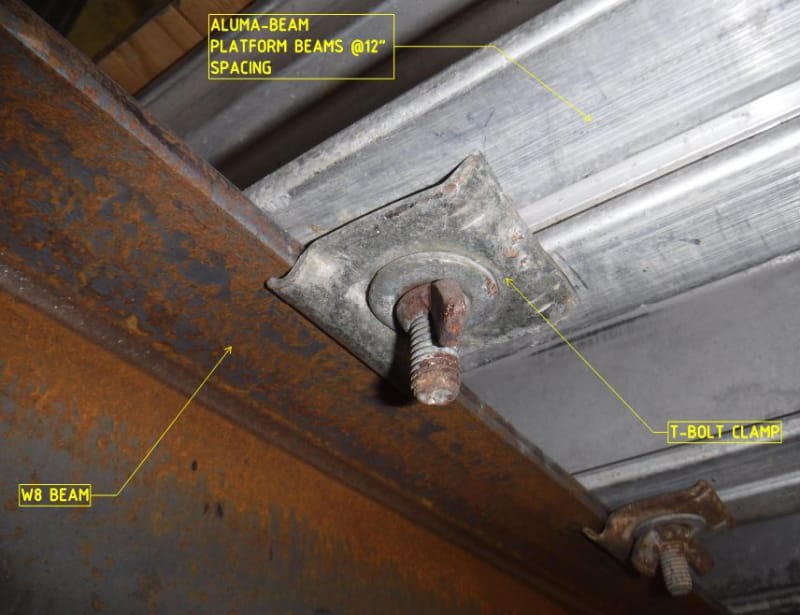
Problem is the alum-beam joists are connected to the W8 top flange via a single T-bolt friction clamp per joist. See annotated photo below.

The platform is limited-access, with reduced headroom, with no materials storage and LL limited to 50 psf.

Anyone got any references/data/resources such that I can put a number on this clamp capacity?

CaptureLTB_kzicxb.jpg
 
I believe that some of the manufacturers have test data on the slip load of these clamp assemblies, though the tests would be based on both components being made by the same manufacturers, and the reality is the aluminum joists often get mixed up over time. Hard to know for sure, but in the photo it appears that the T - bolt may be a Safway ABC clamp, and it could be Safway joists. If you could confirm the manufacturer of each, and they are the same, it might be possible to get the information from their engineering department. And if necessary, in some circumstances, they are used on both sides of the W8, which can help.

Only other option that occurs to me is to add a supplemental member in between joists, that you could design to brace the top flange of the W8. Depending on access, might be difficult to install.

And for what it is worth, a 20' span on the aluminum is significant, especially if the aluminum member is a standard 6 1/2" depth. These are usually max'd out at about 10' spans, when used as concrete falsework (with higher loads). So I would recommend confirming that they are also adequately braced laterally.
 
In formwork, simple friction is often all we get for bracing many loads. The questions usually become challenges when we take things to an aggressive limit - obviously these are very subjective terms.

The beam needs bracing when it sees its full load - the gravity loads impart their max load at max load (of course) so what magnitude of friction force can you identify solely from the loading being applied via the Aluminum vs. 2% - 10% of the in place dead load (or total load in light of your live load only case)?


Also, can you temporarily restrict use while the bracing is off or introduce temporary bracing between the existing aluminum to carry loads back to the other bracing system.


The 20' span is a bold one to me, but certainly is not out of the question where strength is the only concern and larger deflections are acceptable to the end user.

Most formwork material design guides have a limited statement on bracing or no real insight and are based on a 2:1 or 2.2:1 FOS. The question of if OSHA requirements are the governing case and a change in FOS is another question.
 
Ingenuity said:
...temporary construction access platform...
...any references/data/resources such that I can put a number on this clamp capacity?

I would:

1) Assume a conservative finger-tightened torque for the wing nuts shown in the photo.

2) Use the (approximate) equation for converting nut torque to bolt tension. With a conservative assumption for "torque coefficient", calculate tension.

3) Divide the result of "Step 2" by two. This is to account for the geometry of the clamp shown in the photo - force applied to the beam is assumed to be half the tension in the bolt, due to lever action.

4) Assume a conservative value for the coefficient of friction to calculate allowable allowable lateral load on the clamp-to-beam interface.

5) Apply the (approximate) "two percent rule" to calculate allowable compression force in the beam flange.

With the conservative assumptions I used, one clamp is good for bracing a load > 700 lb... and there is both plenty of redundancy (clamps located every 12") plus friction of the alum-beam joists on the steel beams.

[idea]
[r2d2]
 
I do have a page from one of the big Alumanum formwork vendors that gives a 500lb sliding capacity with a 3:1 FOS, but no specific torque value. I'd assume snug tight plus a quarter turn or anything less than snapping off the bolt.

 
The problem with something like that is knowing how much it's "pinching".....and since there is no reliable way to know....I'd disregard it.
 
If the clamps are installed at 12" o/c on both sides of the flange, I believe the beam may be considered laterally braced. If they are on one side only, I would not consider the beam to be laterally braced.

The beams are W8 but there are several different weights in the W8 family, each with a different value of Lu. A W8x13 has an Lu value of 1340mm or 52.75". Heavier shapes have a larger value for Lu. SlideRuleEra mentioned the 2% rule which states that a lateral brace spaced at Lu must have enough capacity to resist 2% of the compression in the top flange of the beam it is bracing. But in this case, there are four or more braces within the length of Lu.

To prevent lateral torsional buckling, the top flange must be prevented from deflecting laterally OR the beam must be prevented from rotating at the brace point. It is difficult to see how the beam in the photo could rotate or translate if it is braced at 12" centers ON BOTH SIDES of the beam flange.

BA
 
Thank you all for the detailed and informative replies.

jjl317 said:
...the T - bolt may be a Safway ABC clamp, and it could be Safway joists

You got it in one - both are indeed SAFWAY components. I have a call into SAFWAY and their engineering department and they are going to send me capacity data.

DTGT2002 said:
The 20' span is a bold one to me, but certainly is not out of the question where strength is the only concern and larger deflections are acceptable to the end user.

jjl317 said:
And for what it is worth, a 20' span on the aluminum is significant, especially if the aluminum member is a standard 6 1/2" depth. These are usually max'd out at about 10' spans, when used as concrete falsework (with higher loads). So I would recommend confirming that they are also adequately braced laterally.

It is actually closer to 18' - one of the beams was relocated to miss a future obstruction - SAFWAY designed/installed the alum beam platform. There is 3/4" plywood sheathing/decking.

DTGT2002 said:
Also, can you temporarily restrict use while the bracing is off or introduce temporary bracing between the existing aluminum to carry loads back to the other bracing system.

We can temporarily restrict access, BUT very difficult to get access below the platform deck as it is now about 30 feet to the next floor below - two floors of slab were cut and removed for a feature stairway, below.

DTGT2002 said:
I do have a page from one of the big Alumanum formwork vendors that gives a 500lb sliding capacity with a 3:1 FOS, but no specific torque value. I'd assume snug tight plus a quarter turn or anything less than snapping off the bolt.

SRE said:
With the conservative assumptions I used, one clamp is good for bracing a load > 700 lb...

Thanks DTGT and SRE - similar numbers. I like your 'first principles' approach, SRE.

BAretired said:
If the clamps are installed at 12" o/c on both sides of the flange, I believe the beam may be considered laterally braced. If they are on one side only, I would not consider the beam to be laterally braced.

The are currently installed on one side only, and that is what I recommended they do is install on both sides, IF I can make the 'numbers' work.


===> UPDATE: 10/9/2018:

I received this reply from SAFWAY:

SAFWAY said:
The ABC clamp is designed to hold the aluminum beams in place during erection and dismantle, it is not intended to resist intentionally applied horizontal loads. BrandSafway does not provide slip capacity load ratings for the ABC clamp because the clamp...not designed for that purpose.


Ingenuity said:
The W8's are 35 ft long - continuous spans...

Have you taken a look at the proposed loading and support locations for the W8s?

Depending on how the loading is distributed, the compression flange probably alternates between the top flange and bottom flange... reducing the effective unbraced length.

Also, if the W8's bending stress is low enough, allowable unbraced length can exceed Lu by a pretty large amount. I have had occasion to design and use lightly loaded beams with seemingly ridiculous unbraced lengths... they worked as predicted by the math.

[idea]
[r2d2]
 
SRE said:
Have you taken a look at the proposed loading and support locations for the W8s?

Depending on how the loading is distributed, the compression flange probably alternates between the top flange and bottom flange... reducing the effective unbraced length.

Also, if the W8's bending stress is low enough, allowable unbraced length can exceed Lu by a pretty large amount. I have had occasion to design and use lightly loaded beams with seemingly ridiculous unbraced lengths... they worked as predicted by the math.

Yes, it was the first thing I 'played' with before I tried to use the alum beam friction clamps.

The difficulty with the continuous supports are that they are hanger supports - supports using tension member angles attached to top flange of W8's and connected to the concrete roof above. Until the recent modifications, there was direct lateral restraint at each hanger location. Loosing the lateral restraint effectively makes my unbraced length equal to the full beam length of 35 ft.

Looking probable that I will provide a new horizontal lateral brace (HSS back to the other W8 that is directly braced) at one of the internal hanger supports making my unbraced length of this W8 about half of the 35 feet.

Thanks for your comments/assistance, SRE.
 
Inginuity said:
Looking probable that I will provide a new horizontal lateral brace (HSS back to the other W8 that is directly braced) at one of the internal hanger supports making my unbraced length of this W8 about half of the 35 feet.

My gut feel would be to do the same, regardless of what follows. Statistically, people get hurt building structures, not occupying them. I like to play it safe with construction safety.

BAretired said:
To prevent lateral torsional buckling, the top flange must be prevented from deflecting laterally OR the beam must be prevented from rotating at the brace point. It is difficult to see how the beam in the photo could rotate or translate if it is braced at 12" centers ON BOTH SIDES of the beam flange.

I echo this statement with slight modification. As I doubt the demonstrable capacity of any available diaphragm here, I would be inclined to look at the aluminum members as rotational bracing only rather than either rotational or translational bracing. Like BA though, I would also consider clips on both sides of the flange to be adequate for this purpose. I'd probably be willing to stand by that regardless of what SAFWAY has to say about it. You'll have connection capacity in the vertical direction because, obviously, that's what the clips are designed to do. With regard to the beam flange slipping away from the clips laterally, the clips on one side of the flange will act is a "stop" in compression. So no need to get into friction fundamentals there. I suspect that, in reality, just providing clips on the inside of the beams would get the job done here as the load would encourage the beam flange to LTB in that direction. That is, admittedly, a bit of a sketchy thing to hang your hat on so we'll not do that.

Inginuity said:
The difficulty with the continuous supports are that they are hanger supports - supports using tension member angles attached to top flange of W8's and connected to the concrete roof above. Until the recent modifications, there was direct lateral restraint at each hanger location. Loosing the lateral restraint effectively makes my unbraced length equal to the full beam length of 35 ft.

I'm not convinced that this is a real difficulty. Your reaction force will be delivered to the beam tension flange in a way that inherently aids stability. Fancy math aside, I struggle to envision the beam bottom flange rotating upwards in space in an LTB mode. Not much potential energy shedding in that. Even better if you could get stiffeners in the beam at this location and engage a bit of the hanger angle flexural stiffness to provide rotational bracing.

I like to debate structural engineering theory -- a lot. If I challenge you on something, know that I'm doing so because I respect your opinion enough to either change it or adopt it.
 
Ingenuity, have you considered some kind of weld of the clips (in place) to the members involved? I don't know if the thicknesses involved will allow that to happen or not......but if the moments involved are not that great, perhaps you wouldn't have to do it to every clip.
 
Status
Not open for further replies.

Part and Inventory Search

Sponsor

Back
Top