Continue to Site

Eng-Tips is the largest engineering community on the Internet

Intelligent Work Forums for Engineering Professionals

  • Congratulations waross on being selected by the Eng-Tips community for having the most helpful posts in the forums last week. Way to Go!

Large Deflection of Thin Aluminum Panels - Looking for a Spreadsheet-able Approach 1

Status
Not open for further replies.

KootK

Structural
Oct 16, 2001
18,590
I would like to produce some deflection vs uniform pressure diagrams for a 3mm thick aluminum panel product. I mistakenly thought that this would be easy and it's turned out to be rather difficult. I'm hoping that someone can either a) point me to a suitable method or b) confirm that no such method exists. Some thoughts/background:

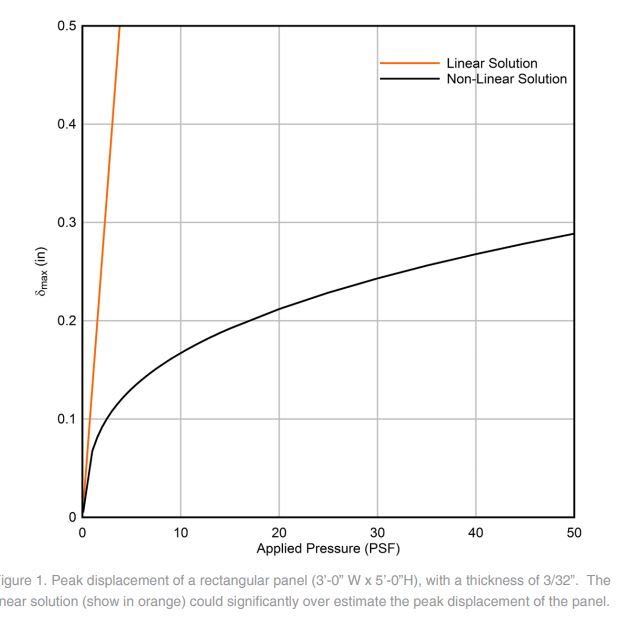
- Per the graph below, non-linear membrane actions factor in significantly. I've erroneously used Timoshenko's small deflection equation to produce what is effectively my own version of the straight line. When I got to looking at the deflections, I realized that they greatly exceed the member thickness.

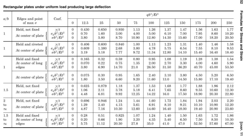
- Resource wise, I've got Timoshenko's plates and shells, Roarks, and most of the old papers cited in Roarks.

- While I don't need this to be super easy/simple, I don't want to get into FEM or Finite Difference with this. I also don't want to be assuming shape functions and doing virtual work in the form of variational calculus. This kind of thing is mentioned in the papers cited in Roarks. I'm sure that it's great stuff but I'm afraid that my math skills are not of a caliber that I'd trust myself to attempt this kind of a solution and pass it off to my client as results in which I was confident.

- Even if I can find a reasonable method to account for the membrane action, I suspect that most such solutions would assume the pinned supports to provide perfect in plane restraint to the panel edges. I doubt the truthiness of that in most applications. And assessing the surrounding structure for its contribution to membrane deformation would increase the scope of this assignment substantially. I know that, in many cases, panels can sort of create their own compression ring from which the membrane can be suspended. No doubt that's what happens with metal panel but, again, accounting for it simply seems to be a pretty tall order.

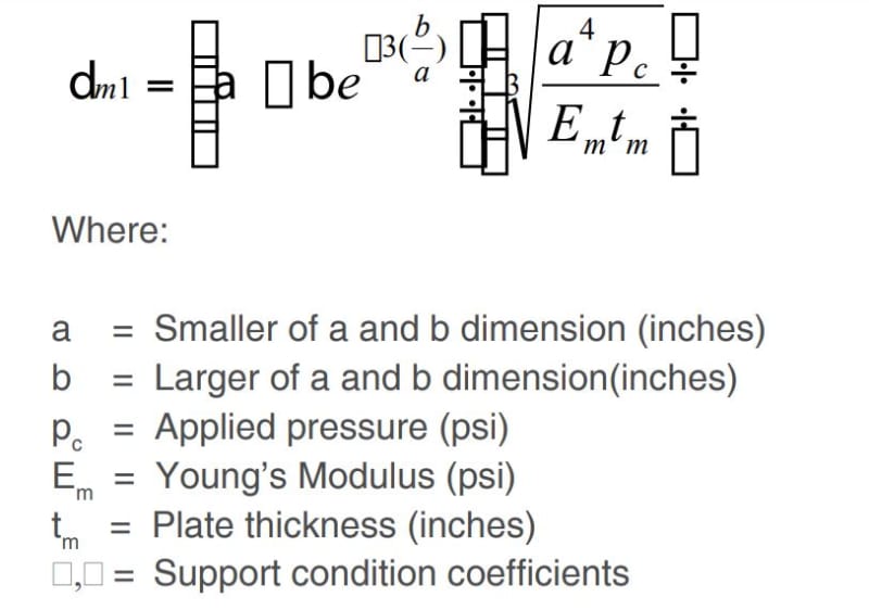
- I stumbled upon this document by Enclos. They actually propose a formula for this scenario but the equation got all jumbled on the greek variables. Anybody know what this equation is supposed to be?

c01_wqnj7o.jpg

c02_grstrt.jpg


I like to debate structural engineering theory -- a lot. If I challenge you on something, know that I'm doing so because I respect your opinion enough to either change it or adopt it.
 
Replies continue below

Recommended for you

Do the large-deflection tables in Roark help? Page 407 and 408 in the 5th Edition.
Generally, for plate design, ignoring tension in the plate is conservative.
If the problem can be treated as 2-D, it simplifies it.
 
JStephen said:
Generally, for plate design, ignoring tension in the plate is conservative.

Agreed. Much too conservative in this instance however.

JStephen said:
Do the large-deflection tables in Roark help? Page 407 and 408 in the 5th Edition.

Do you mean the table below from the 7th ed? It's a step in the right direction but I'm hoping to hit a few more aspect rations. Also, poisson is 0.312 whereas I need 0.33. Small difference probably. And I may be able to figure out how to adjust for that. I guess part of my hang up is that the table may not spreadsheet all that easily. Color me lazy.

steele6707 said:
ttached are a few pages from "Advanced Strength of Materials" by J. P. Den Hartog - Dover publications. There are some problems (not worked) and solutions if you are interested.

Thanks for that Don. I'd would be interested in the examples if any are rectangles with uniform loads.

c01_nqzy7j.jpg


I like to debate structural engineering theory -- a lot. If I challenge you on something, know that I'm doing so because I respect your opinion enough to either change it or adopt it.
 
UFC 3-340-02 Chapter 3 has formulas for plate deflections based on yield line theory. It treats the plate and boundary conditions as an equivalent single degree-of-freedom system, with formulas for elastic and post-yield deflections. I believe it has methods for incorporating tension-membrane action as well, but I've always neglected that.
 
Have you reached out to Enclos to see if they have a copy of the linked "Insight" that doesn't have a jumbled equation?
 
Kootk, you could have a look here: it's a rectangular plate with supported but unheld sides, a case that's not treated by that table in Roark. The solution is obtained by minimization of the strain energy, not exactly what you say to be prepared to face; I don't think, however, that a single formula could cover all different condtions (aspect ratii, held-unheld, etc.). You could calculate yourself a number of cases and build a table or an interpolation formula.
What you mention, a panel that has supported or unsupported sides, where the sides are stiffened, is not treated at xcalcs nor elsewhere: it could however be solved with the energy method.

prex
[URL unfurl="true"]http://www.xcalcs.com[/url] : Online engineering calculations
[URL unfurl="true"]https://www.megamag.it[/url] : Magnetic brakes and launchers for fun rides
[URL unfurl="true"]https://www.levitans.com[/url] : Air bearing pads
 
I've been watching this post for the past few days to see what suggestions others have provided. I don't know how many other engineers have been involved with static and dynamic wind pressure testing on 3mm aluminum plate or 4mm aluminum composite material, but I've designed and conducted quite a few of these tests. Here are some of my observations from the actual pressure tests:

1. In general terms, the plates do not deflect as much as calculated when using Roarks deflection coefficients based off of the plates boundary conditions. KootK, like you mentioned in a previous post I think most of this can be addressed through membrane action.

2. After the plates have been loaded in both the static and dynamic pressure tests I have seen quite a few plates that didn't meet the permanent set deflection criteria for these tests. Based off of this information it leads me to believe that the plates were stressed beyond the elastic deformation range. When you compare the Roarks stress values for these scenarios, Roarks would indicate that the plates would should not become overstressed and should recover to their original state. Again, this makes sense with regards to membrane action.

Based off of this information I do feel that large deflection formulas would be more appropriate to model the plates actual behavior. However there aren't many clean and easy formulas that engineers can quickly utilize, especially when analyzing non-structural cladding elements.

All that being said, I've seen quite a few of the leading US consulting engineering firms and manufacturers use the Roarks formulas to quickly analyze the plates and their performance. I'm not saying this is the best solution, but I wanted to paint the picture of real world results versus what the majority of others in this industry are currently doing.
 
We use alot of 3/16 alum (4.7mm). I do recall that (in general) the calculated deflections are more then that measured for these plates. They are tested by walking on them or using 300lbs wieghts and measuring deflection as they are used in walkways. So they 'normally' do not like to stress the products beyound their apparent yield points, cause if I bend them they do not sell it. In these cases actual stress and safety factor is measured by the deflection. It is disconcerting to read that the calculated stress is non conservative and the opposite of the calculated deflections which are conservative.

I have bent enoough products of the thicker materials to confirm that calcs are closer to actual measurements with thicker materials.
 
Thanks all for the assistance thus far.

Shotzie said:
Have you reached out to Enclos to see if they have a copy of the linked "Insight" that doesn't have a jumbled equation?

I did, about a week ago. Haven't heard anything back yet but, then, I can't imagine that they're in a big hurry to give away trade secrets to competitors.

klause said:
Why not use FEM ?

Time and money. Since I'm looking for quick and dirty data curves rather than the assessment of specific conditions, there would be rather a lot of effort involved in creating and evaluating a bunch of FEM models.

brut3 said:
All that being said, I've seen quite a few of the leading US consulting engineering firms and manufacturers use the Roarks formulas to quickly analyze the plates and their performance

By this, you mean the Roarks large deflection equations, right?

If this was something that I had to do regularly, I think that I might just program it into mathCAD as rudimentary FEM or finite difference method. Automating runs for uniformly loaded rectangles can't be that hard.

I like to debate structural engineering theory -- a lot. If I challenge you on something, know that I'm doing so because I respect your opinion enough to either change it or adopt it.
 
Once upon a time a large car company used a membrane design for the spare wheel well. They developed the shape by using a rubber sheet. Perhaps the quickest method for your particular aspect ratio would be a rubber sheet, a frame ,and an air compressor.

Cheers

Greg Locock


New here? Try reading these, they might help FAQ731-376
 
KootK said:
By this, you mean the Roarks large deflection equations, right?

I should have clarified. I see the small deflection equations in table 11.4 (Roarks Formulas for Stress and Strain - 8th Edition) referenced most frequently. Below is a link to Alpolic by Mitsubishi's technical bulletin which describes how they typically analyze their panels (plates) and it utilizes the 11.4 tables.

 
Koot,

I've always run with the Roarkes formula 11.4. It is a conservative approach. But there is no better easy way for pounding out quick deliverables. If you model the panel as a shell with FEM, you can tighten up the deflections with the inclusion of membrane stiffness. I don't often do this - if aluminum panel contractors were hounding me to reduce panel stiffener spacings, I would be digging into it further. but they're not, so I'm not.

This is similar in concept to my issues with SJ Mepla that you and I hashed out a while back- I don't believe their program included membrane forces (though they claim they do). SJ mepla estimated deflections much larger compared to similar modeling of plates in other FEM that included membrane action (which is bull for a program that costs 5000 euro). I think SJ mepla might model aluminum plates as well? I've since moved on to an outfit that does not have Mepla on hand.

There may be a case for these aluminum sheet manufacturers to do some testing for the engineering community so we could refine things, but I'm pretty sure they're much too tied up with dealing with all the fire issues at the moment.

I would share the spreadsheet i have, but its tricky as it doesnt fully belong to me.

hope this helps. cheers
 
Status
Not open for further replies.

Part and Inventory Search

Sponsor